6-2
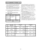
SELF-DIAGNOSIS DISPLAY
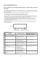
Mechanism Mode Display / Head Output Drop Warning Display / Cylinder Rotation Accumulated
Time Display
This unit displays the diagnosis contents of abnormalities and the mechanism, mode on its display panel in 2-digit numbers.
When the head playback output has dropped, the “ L” sign will be blinked. Some models (listed later) will also display the cylinder
rotation accumulated time.
These display shows the outline of the problems. Use it as a reference when servicing the unit.
1. Self-Diagnosis Contents and Mechanism Mode Display
• When the STOP button on the remote control is pressed for about 10 seconds continuously, the self- diagnosis number
will be displayed on the reception channel display of the display panel and number indicating the failed mechanism mode
(changed mode when being shifted) on the tape counter “seconds” display for 10 seconds each.
• During self-diagnosis display, displays other than the diagnosis number/mechanism mode number and the cylinder
accumulated rotation time display described later (some models only) will be turned off and when displays end, the
normal display will be returned automatically.
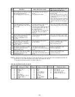
• Refer to “Self-Diagnosis Contents” for the self-diagnosis numbers and the “Mechanism Mode Display Contents” for the
mechanism mode numbers.
• When the “0” button on the remote control unit is pressed during display, and clearing the self-diagnosis display and
mechanism mode display.
No.
Problem
Main Possible Cause
Mechanism Operations and
State After Occurrence
00 There is no abnormality in the mechanism.
The cylinder motor does not rotate.
• The cylinder motor is faulty.
Shifts to the STOP mode.
01
• The control of the cylinder motor is
faulty.
• The tape winds around the cylinder.
The take-up reel does not rotate.
• The take-up reel is caught.
Shifts to the STOP mode.
02
• The reel belt is faulty.
• The take-up torque has decreased.
The capstan motor does not rotate.
• The capstan motor is faulty.
Shifts to the STOP mode.
03
• The control of the capstan motor is
fauIty .
The tape cannot be loaded with the
• Error in the operations of the tape
Unloads, shifts to the INITIAL mode,
cassette inserted.
loading mechanism.
and the power goes off.
(But unloading can be performed.)
• Foreign particles in the tape
04
loading mechanism.
• The tape end sensor is faulty.
• The reel brake of the tape cassette
has not been released.
Tape loading and unloading cannot
• The tape guide is caught.
The power is forcibly turned off with
05
be performed with the cassette
• The loading motor is faulty.
the mechanism at its current position.
inserted.
• The control of the loading motor is
faulty.
Self-Diagnosis Contents
Display panel
Self-Diagnosis number
(Reception channel display)
Mechanism mode number
(Tape counter “Seconds” display)
Содержание SLV-L45AR
Страница 6: ...1 2 ...
Страница 7: ...1 3 ...
Страница 8: ...1 4 ...
Страница 9: ...1 5 ...
Страница 10: ...1 6 ...
Страница 11: ...1 7 ...
Страница 12: ...1 8 E ...
Страница 17: ...3 2 MECHANISM CONNECTION DIAGRAM ...
Страница 18: ...3 3 3 4 SLV L45AR L65HFAR L75HFAR OVERALL WIRING DIAGRAM SLV L45AR ...
Страница 19: ...SLV L45AR L65HFAR L75HFAR OVERALL WIRING DIAGRAM SLV L65HFAR L75HFAR 3 5 3 6 ...
Страница 20: ...3 7 3 8 SLV L45AR L65HFAR L75HFAR SYSTEM CONTROL SERVO CIRCUIT DIAGRAM SLV L45AR ...
Страница 21: ...3 9 3 10 SLV L45AR L65HFAR L75HFAR SYSTEM CONTROL SERVO CIRCUIT DIAGRAM SLV L65HFAR L75HFAR ...
Страница 22: ...3 11 3 12 SLV L45AR L65HFAR L75HFAR VIDEO CIRCUIT DIAGRAM SLV L45AR AUDIO CIRCUIT DIAGRAM SLV L45AR ...
Страница 25: ...SLV L45AR L65HFAR L75HFAR 4 3 4 4 CP 1 BOARD VA A VIDEO AUDIO TUNER CIRCUIT DIAGRAM SLV L45AR ...
Страница 26: ...SLV L45AR L65HFAR L75HFAR 4 5 4 6 CP 1 BOARD VA A VIDEO AUDIO TUNER CIRCUIT DIAGRAM SLV L65HFAR L75HFAR ...
Страница 27: ...SLV L45AR L65HFAR L75HFAR 4 7 4 8 VIDEO CIRCUIT WAVEFORMS VP 1 BOARD VIDEO PRE AMP CIRCUIT DIAGRAM SLV L45AR ...
Страница 32: ...SLV L45AR L65HFAR L75HFAR 4 17 4 18 CP 1 BOARD SY A SYSTEM CONTROL SERVO CIRCUIT DIAGRAM SLV L45AR ...
Страница 33: ...4 19 4 20 CP 1 BOARD SY A SYSTEM CONTROL SERVO CIRCUIT DIAGRAM SLV L65HFAR L75HFAR ...

