27
Connection with ILME-FR7
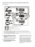
The following diagram shows a connection example for operating an ILME-FR7.
Remote control signal: LAN straight cable (Category 5e or higher)
Tally/contact signal: Connection cable
*1
Video signal: Connection cable with BNC connectors or HDMI cable
Signal flow
Wi-Fi router
Video switcher
Web app
*1 Use a connection cable designed for the switcher being used. For the specifications of the GPI I/O connector
of the unit, see “Pin assignments” (page 83).
Switching hub
Tablet
To video monitor
RM-IP500
ILME-FR7
SDI or
HDMI
LAN
ILME-FR7
SDI or
HDMI
LAN
Содержание RM-IP500
Страница 86: ...Sony Corporation ...

