2-11. IO-255 Board
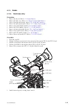
Preparation
1.
Remove the battery lid. (Refer to
2.
Remove the bottom cover. (Refer to
“2-3. Bottom Cover and Tripod Washer”
.)
3.
Remove the inside panel assembly. (Refer to
“2-4-1. Inside Panel Assembly”
.)
4.
Remove the outside panel assembly. (Refer to
“2-5-1. Outside Panel Assembly”
.)
5.
Remove the top panel assembly. (Refer to
6.
Remove the SxS slot assembly. (Refer to
7.
Remove the front panel assembly. (Refer to
8.
Remove the rear panel assembly. (Refer to
.)
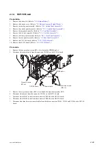
Procedure
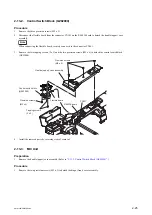
1.
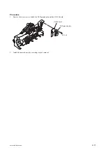
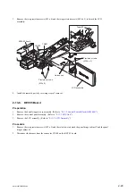
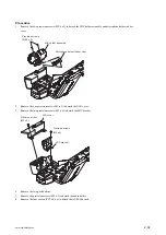
Peel off the tape (BT).
2.
Disconnect the flexible flat cable from the connector CN2201 on the DCP-56 board.
3.
Disconnect the coaxial cable from the IO-255 assembly.
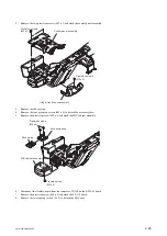
4.
Remove the two precision screws (M2 x 4) to detach the IO-255 assembly.
Tape (BT)
Coaxial cable
IO-255 assembly
CN2201 (DCP-56 board)
Flexible flat cable
Precision screws
(M2 x 4)
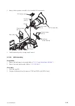
5.
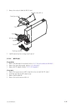
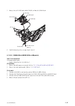
Unsolder the coaxial connectors (BNC type) on the IO-255 board.
6.
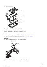
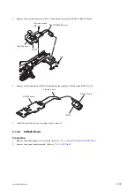
Remove the IO-255 board in the arrow direction, and then remove the coaxial connectors (BNC type) and the V-
OUT spacer.
PMW-200/PMW-EX280
2-20
Содержание PMW-200
Страница 1: ...SOLID STATE MEMORY CAMCORDER PMW 200 PMW EX280 SERVICE MANUAL 1st Edition Revised 1 ...
Страница 4: ......
Страница 8: ......
Страница 10: ......
Страница 30: ......
Страница 38: ...3 Install the removed parts by reversing steps of removal PMW 200 PMW EX280 2 8 ...
Страница 82: ......
Страница 96: ......
Страница 122: ...Lens Block Assembly 1301 No Part No SP Description 1301 A 1911 477 A s FRONT ASSEMBLY RP PMW 200 PMW EX280 5 16 ...
Страница 128: ......
Страница 130: ......
Страница 132: ......
Страница 133: ......


