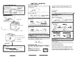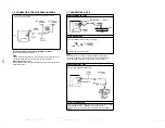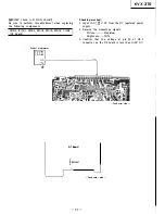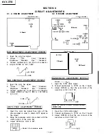
!SIGNAL DC ADJUSTMENT (RV8106)
I
1.
Input the 100
%
white signal.
2.
Connect oscilloscope to TP701 on the C board.
3.
Adjust RV8106 so that
O IRE
level of the
waveform is 19.5 ± 0.5V DC.
M
±0.5V
DC.
GND
jvco
ADJUSTMENT (CTaoo1)
I
1.
Input the 100
%
red signal.
2.
Connect digital multimeter to TP8004.
3.
Adjust CT8001 for 2.3
±
0.2V DC.
jRUN IN LEVEL ADJUSTMENT (RV8005)
I
1.
Input the 100
%
red signal.
2.
Picture············Max.
Brightness······· Max.
3.
Adjust RV8002 for maximum level.
4.
Connect oscilloscope to TP8006.
5. Set the low level neither point A or B to
3.4V DC.
6. Confirm that the peak voltage is 6.5 Vp-p or less
and at this time there is no error.
BANDPASS TRANSFORMER ADJUSTMENT
(T800t)
1.
Input the cross hatch signal.
Picture·········••• Max.
Brightness·······Standard
2.
Connect oscilloscope to TP8003 through the filter.
3.
Adjust TP8001 as shown in figure.
I
4:lk / Oscilloscope
TP8003�
j
330p;J;
-r:v
-r-v
(Adjust with the vicinity
of the V period center}
LINEARITY MIX AND LINEARITY DELAY
(RV8003, RV8004)
1.
Input the 100
%
red signal.
KVX-370
2.
Connect oscilloscope to pin ® of IC8002 through
the filter.
IC8002 10K
@pin �
. J;
0.022µ
(Filter)
3.
While observing the waveform with V interval,
tum RV8003 slowly until oscillation starts then
back out RV8003 slowly and stops where
oscillation ceases.
4. Tum RV601 on the D2 board until oscillation
starts then back out slowly and stops where
oscillation ceases.
5.
Readjust RV8003 in a similar manner in step (3).
6.
Connect oscilloscope to TP8003 through the filter.
B board 4.7k
TP800
3
�
l33o
p
(Filter)
7.
Adjust RV601 on the D2 board for maximum
amplitude.
8.
While observing the waveform with V interval,
adjust RV8004 for minimum amplitude.
9.
Observe the waveform with H interval (near
center of V interval), reduce the transient pulse
at the start of H interval with RV8006.
10. Set RV601 on the D2 board to mid-range.
RED DRIVE AND BLUE DRIVE ADJUSTMENTS
(RV8107, RV8108)
1.
Input the 100
%
white signal.
2.
Connect oscilloscope to TP701 on the C board
using 100: 1 probe.
3. Adjust RV8107 and RV8108 so that the peak
voltage of red, green and blue are equal.
I
LANDING ADJUSTMENT (RV8001)
I
1.
Input the 100
%
red signal.
2.
Adjust RV8001 for best red · on the screen.
13-
KVX-370
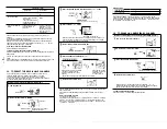
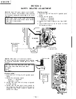
4-3. 01 BOARD ADJUSTMENT
01 Board
RV1502
©
RV1501
TP1502 0
@
Conductor side -
IHV VOLTAGE ADJUSTMENT (RV1501)I
1.
Input the color bar signal.
1.
Picture············Max.
Brightness······· Max.
3.
Connect digital multimeter (input impedance: 100
M
Q
or more) to TP1502.
4.
Adjust RV1501 for 9.2
±
0.05V.
I
FOCUS ADJUSTMENT (RV1502)
I
1.
Input the 100
%
red signal.
2. Picture····· ·······Max.
Color······ Standard
Brightness·······Standard
Hue ········ Standard
3.
Adjust RV1502 for uniform red on the screen.
4-4. 02 BOARD ADJUSTMENT
RV603
02·1
@RV602
@RV601
Conductor side -
0
TP601
02 Board
02-3
-Conductor side -
l
•=••
I
0
TP8003
TP8005
0
B Board
!CATHODE BIAS ADJUSTMENT (RV603)
I
1.
Input the color bar signal.
2.
Connect digital multimeter to TP601 (or TP8005
on the B board).
3.
Adjust RV603 for 4.0 ± 0.2V DC.
IH
SAW ADJUSTMENT (RV602)
I
1.
Input the 100
%
red signal.
2.
Connect oscilloscope to TP8003 on the B board
through the filter.
3.
Adjust RV602 to flat the envelope waveform.
Flat
B board o 4:?.
K
O 'II
TP8003
m
1
SCI
oscope
330P
.l
re
I,
.I
(Filter)
H
interval
H LINEARITY SERVO GAIN ADJUSTMENT
(RV601)
1.
Input the 100 % red signal.
2.
Connect oscilloscope to TP8003 on the B board.
3.
Turn RV601 until oscillation occurs then turn
slowly and stops where oscillation ceases.
4. Confirm that there is no oscillation on the screen
and both right and left sides on the screen is
uniform red.
Stop oscillation.
1..
• I
V
interval
-1A-
4-5. 03 BO
-Conduct
03 Boi
VERTICAL.
(RV681)
1.
Input the
Picture····
Brightnes
2.
Adjust R
p.14


