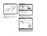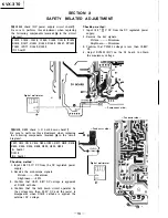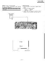
ductor side -
(RV603) I
i0l (or TP8005
]
n the B board
pe waveform.
Flat
·val
n the B board.
:urs then tum
n ceases.
l on the screen
1 the screen is
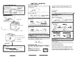
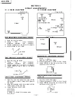
4-5. D3 BOARD ADJUSTMENT
- Conductor side -
R681
@
D3 Board
VERTICAL AMPLITUDE ADJUSTMENT
(RV681)
1. Input the. inonoscope signal.
Picture············Max.
Color ······ Standard
Brightness·······'Standard
Hue ········ Sta�dard
2. Adjust RV681 for 11.5 ± 0.25 frame.
I_
l<VX-370
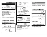
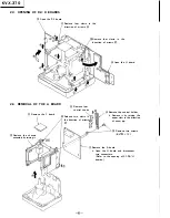
4-6. B BOARD AND H BOARD ADJUSTMENT
I
I
©
RV002
@
RV003
@
RV004
H Board
B Board
- Conductor side -
t..._r---
- Conductor side -
RV8107
©©
RV8108
I
WHITE BALANCE ADJUSTMENT
(RV002,RV003, RV004, RV8107, RV8108)
CUT-OFF ADJUSTMENT (H BOARD)
1. Input the color bar signal then turn off the
chroma signal in order to obtain B/W signal on
the screen.
2. Picture······Max.
Hue ·············· Standard
Color···--····Standard
Brightness .... Standard
3. Adjust RV002 (RED), RV003 (GREEN) and RV004
(BLUE) so that the best possible white balance
is obtained at the second stripe from the right
of the color bar signal.
DRIVE ADJUSTMENT (B BOARD)
1.
Input the 100 % white signal.
2. Picture······Max.
Hue .............. Standard
Color·········Standard
Brightness .... Standard
3. Adjust RV8107 (red drive) and RV8108 (blue
drive) for the best possible white balance on the
screen.
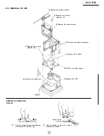
4-7. H BOARD ADJUSTMENT
000
l
H-2
®0®
@RV002
- Conductor side -
@RV005
@RV003
H Board
@RV004
©
RV001
- Conductor side -
�
SW917
gg
SW909
Reserve
t
SW916
OFF
�
RESET
t
I!:!!
M Board
RED, GREEN AND BLUE. OUTPUTS
ADJUSTMENT (RV002, RV003, RV004)
1.
Input the 100 % black (black burst) signal.
2. Connect oscilloscope to pins -@, (J) and ® of
connector H2.
3. Adjust RV002, RV003 and RV004 so that the
pedestal DC voltage of the waveform is 2. 7 ±
0.05V DC.
�.05VDC
_EGND
TIMER DISPLAY POSITION ADJUSTMENT
(RV001)
1.
Set SW916 on the M board to reserve (program)
mode.
2. While pressing SW917 (Alarm) on the M board,
press SW909 (Hour) and display· "12: 00".
A=B
3. Adjust RV00l for A= B.
5V
(Pin
®
of IC003 is 5V.)
47k
11,___.___, Frequency
counter
ITIMER CLOCK ADJUSTMENT (CT001) I
1.
Connect 47 k Q resistor between pin ® of IC003
and 5V then connect frequency counter to pin ®·
2. Adjust CT00l for 2048.000 Hz through 2048.008 Hz.
I PBL ADJUSTMENT .(RV005) I
1. Input the 100 % red signal.
Picture····· ·Max.
Brightness·Standard
Color·········Max.
2. Bring the luminance meter into contact with the
center of screen.
3. Adjust RV005 for 30 ± 2 NIT.
p.15
p.16


