KVX-370
SECTION 4
CIRCUIT ADJUSTMENTS
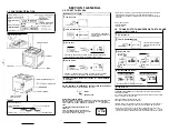
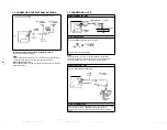
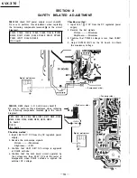
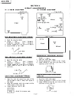
4-1. A BOARD. ADJUSTMENT
- Component side -
o I /\-2
RV305
©
A Board
RV306
©
lsuB BRIGHTNESS ADJUSTMENT (RV305)
I
1. Input the color bar signal.
2. Picture ...... · .... ·Max.
Color ...... Standard
Brightness, ...... standard
Hue ........ Standard
3. Connect oscilloscope to pin ® of A-2 connector.
4. Adjust RV305 for 4.8
±
0.05V.
I
�8±0.05V
�GND
lsuB CONTRAST ADJUSTMENT (RV306)
I
1.
Input the color bar signal.
2. Picture ............ Max.
Color ...... Standard
Brightness .... · .. Standard
Hue ........ Standard
3. Connect oscilloscope to pin ® of A-2 connector.
4. Adjust RV306 so that 0 IRE to 100 IRE is
2.0
±
0.lV.
0 IRE--1\7
/
100
IRE_J_V
!WHITE PEAK ADJUSTMENT (RV306)
I
1. Input the color bar signal then turn off the
chroma signal in order to obtain B/W signal on
the screen.
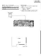
2. Bring the luminance meter into contact with the
white portion of the color bar.
3. Adjust RV306 for 155
±
5 NIT.
�
Cootact the l,mloamoe mete,.
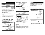
4-2. B BOARD ADJUSTMENT
- Component side -
RV8001
RV8005
©
OTP8006
T8001
] I
I?>.
I
@RV8002
CT8001
YO
TP8003
0
RV8003
@ @
RV8004
B Board
DI
] T�004
RV8006
RV8107
©
@)RV
@
RV8108@
8104
0 TP701
C Board
IC8002
®iJ
�
RV8106
RV8105 �
- Component side -
RV601
©
D2 Board
I
BLANKING DC ADJUSTMENT (RV8104)
I
Picture ...... ·· .... Max.
1. Input the 100 % white signal.
2. Connect oscilloscope to TP701 on the C board.
3. Adjust RV8104 so that the sync level of the
waveform is 8.5
±
0.5V DC.
8.5± 0.5V DC
__.__ _____ GND
RUN IN WHITE LEVEL ADJUSTMENT
(RV8105)
1. Input the 100 % white signal.
2. Connect oscilloscope to TP701 on the C board.
3. Adjust RV8105 so that the run in level of the
waveform is 24.5
±
0.5V DC.
I
r-:=7)
U lt6:�vU
DC
-�.__--GND
-12-


