KVX-370
SECTION 3
SAFETY RELATED ADJUSTMENT
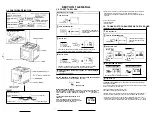
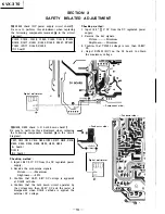
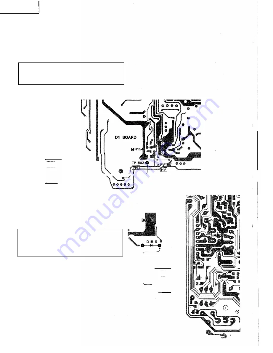
[B R1543 check (HV power supply circuit check)]
Be sure to perform this adjustment when replacing
the following components (marked [:;iii in the circuit
diagram).
C1510, C1515, C1519, C1520, C1533, D1519, IC1502,
R1515, R1517, R1541, Rl542, R1543, R1547, RV1501,
T1501 (FBT), R1540, Ql503
(Dl board)
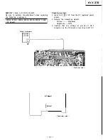
Checking method :
1. Input 15.0 �
8:5
V DC from the DC regulated power
supply.
2. Receive the dot signals.
Picture············ Minimum
Brightness······· Minimum
3. Confirm that TP1502 voltage is less than 10.95V
DC.
4. Adjust RV1501 (HV) on the D1 board to obtain
the maximum voltage.
Digital multimeter
@
1
1
I I�
;J---___.,,_____,.,,---11--+--
--
- Component side -
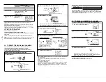
[B R529, R530 check ( + B hold down check)]
Be sure to perform this adjustment when replacing
the following components (marked [:;iii in the circuit
diagram).
C507, C512, C513, C514, D504, IC201, R517, R518, R519,
R522, R523, R524, R529, R530, Q502, Q503
(A board)
D1518
(Dl board)
Checking method :
1. Input 13.5 ± 0.lV DC from the DC regulated power
supply.
2. Receive the monoscope signals.
Picture············ Maximum
Brightness······· 50 %
3. Confirm that 18.0 ± 0.8V DC voltage is appeared
at D1518 cathode.
4. Confirm that the hold down circuit operates by
the voltage less than 25.0V DC and the raster is
disappeared when D1518 cathode is applied the
external DC voltage.
� D1
-10-
- Conductor side -
- Conductor side -
Digital multimeter
l��
I
II
I


