37
No horiz
pincushion
correction
Pix is
bowed
inward
Horizontal Drive / H Pincushion Correc-
tion / Filament Voltage
Overview
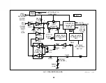
The purpose of the horizontal drive circuit is to manufacture a magnetic
field that is used to sweep the CRT’s electron beam from left to right on
the screen. Within the basic horizontal drive circuit there is a PWM circuit
that supplies the Horizontal Output transistor with voltage and provides
horizontal pincushion correction. The horizontal drive circuit also makes
the CRT filament voltage.
Basic Horizontal Drive Circuit
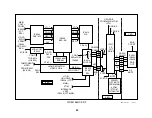
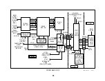
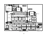
This circuit is split between an oscillator on the A board and an output
stage on the D board. The 33.75kHz horizontal oscillator is in the Y/C
CRT Drive IC201. IC201 outputs a 2Vp-p rectangular waveform from pin
40 while there is B+ at pins 55 & 61 and the 2.7MHz X201 crystal is
running. The horizontal drive waveform is buffered by Q211 and enters
the D board.
On the D board, an N channel MOSFET driver and an output transistor
amplify the signal to provide sufficient current to drive the HOT T5001 and
the H DY deflection yoke.
At the output stage, the HOT T5001 has a secondary winding that pro-
vides filament voltage while its main winding pr200V for the RGB
video output ICs. While the H DY yoke provides horizontal beam deflec-
tion (sweep), a voltage divider consisting of capacitors C5058-C5060 tap
off a sample of the H spike from the H Output Q5030/Collector to start the
HV converter stage. This AFC-PLS is also used in the convergence and
dynamic focus stages.
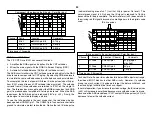
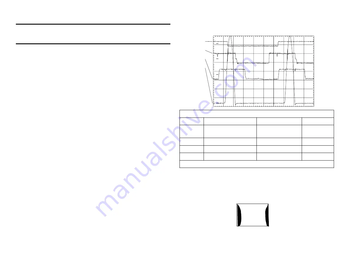
The waveforms of the horizontal drive stage show typical signal shapes.
The difference between this set and a conventional one is that the hori-
zontal frequency is 33.75kHz (ch 2), not 15.75kHz (ch 1). When compar-
ing the input sync (ch 1) to the horizontal oscillator (ch 2), notice that they
are not in phase. This is because the DRC circuit doubled the H fre-
quency, but the MID circuit stored the video and output the signal at a
new H freq. of 33.75kHz, independent of the source.
PM3394, FLUKE & PHILIPS
ch 4
ch 3
ch 2
ch 1
CH1!2.00 V~
CH2!2.00 V~
CH3!10.0 V~ STOP
CH4! 125 V= AL T MTB5.00us L=2 ch2p
1
2
3
4
Horizontal Drive Signals
Channel
Name
Location
Voltage
1
15.75kHz H signal
Input
NTSC generator
from the
generator
2
33.75kHz osc output
IC201/pin 40
2.2Vp-p
3
H Driver input
Q5028/gate
12Vp-p
4
Horiz Output
Q5030/Collector
1kVp-p
Time base = 5usec/div.
PWM Circuit
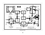
The PWM circuit has two functions. First it provides a regulated 102Vdc
output for the H Output transistor. Second it compensates for horizontal
pincushioning and keeps the picture straight at the sides.
Содержание KV-32XBR400
Страница 1: ......
Страница 5: ...1 NOTES ...
Страница 12: ...8 NOTES ...
Страница 14: ...10 NOTES ...
Страница 83: ...APPENDIX ...

