23
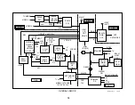
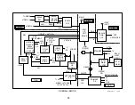
Digital Reality Creation
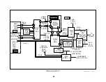
This 3
rd
generation device has three main purposes:
•
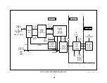
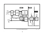
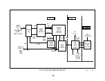
Doubles the number of pixels on each scanning line after analyzing
the pixels in the immediate area.
•
Creates double the number of scanning lines by prediction.
•
Doubles the horizontal frequency to match the new image.
The input is analog component video and the output is an 8 bit parallel
port for each of the three component lines - Y, Pb and Pr. The digital
output goes to the MID circuit IC3408.
Multi Image Driver (MID) Circuit
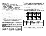
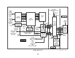
The purpose of the MID circuit is to:
•
Displays two images on the same screen (Main and Sub or Main and
High resolution).
•
Add 60 blank lines to the picture.
•
Change the input signal’s horizontal frequency from 31.5kHz to
33.75kHz.
•
Instruct the related MID uCom IC3090 what the input horizontal fre-
quency is so it can control the sync path and aspect ratio.
Any input signal selected is present at the MID-XA signal processor IC3408,
so it knows what the input horizontal frequency is. Using this information,
the interconnected MID-uCom IC3090 can control the signal and sync
routing as well as send information to the Y/C CRT Drive IC201 for verti-
cal reduction.
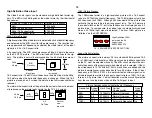
MID-uCom IC3090 Outputs
Name
Destination
Purpose
DO, CO (data, clock)
MID-XA IC3408
Add 60 blank lines
IIC data bus
Y/C, CRT Drive
Vertical Reduction
Sync Sel
Sync Sw IC3413
Sync for IC201
To summarize the MID functions, 60 lines are added to the picture by the
MID-XA main signal processor IC3408 when the horizontal frequency is
not 33.75kHz. MID-uCom IC3090 instructs oscillator IC201 to reduce the
vertical amplitude when the sync is 33.75kHz (High Definition signal).
Signal and Sync Switches
Using control signal from MID-uCom IC3090, switches IC3414 and IC3413
select final signal and sync for the Y/C CRT Drive IC201.
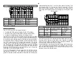
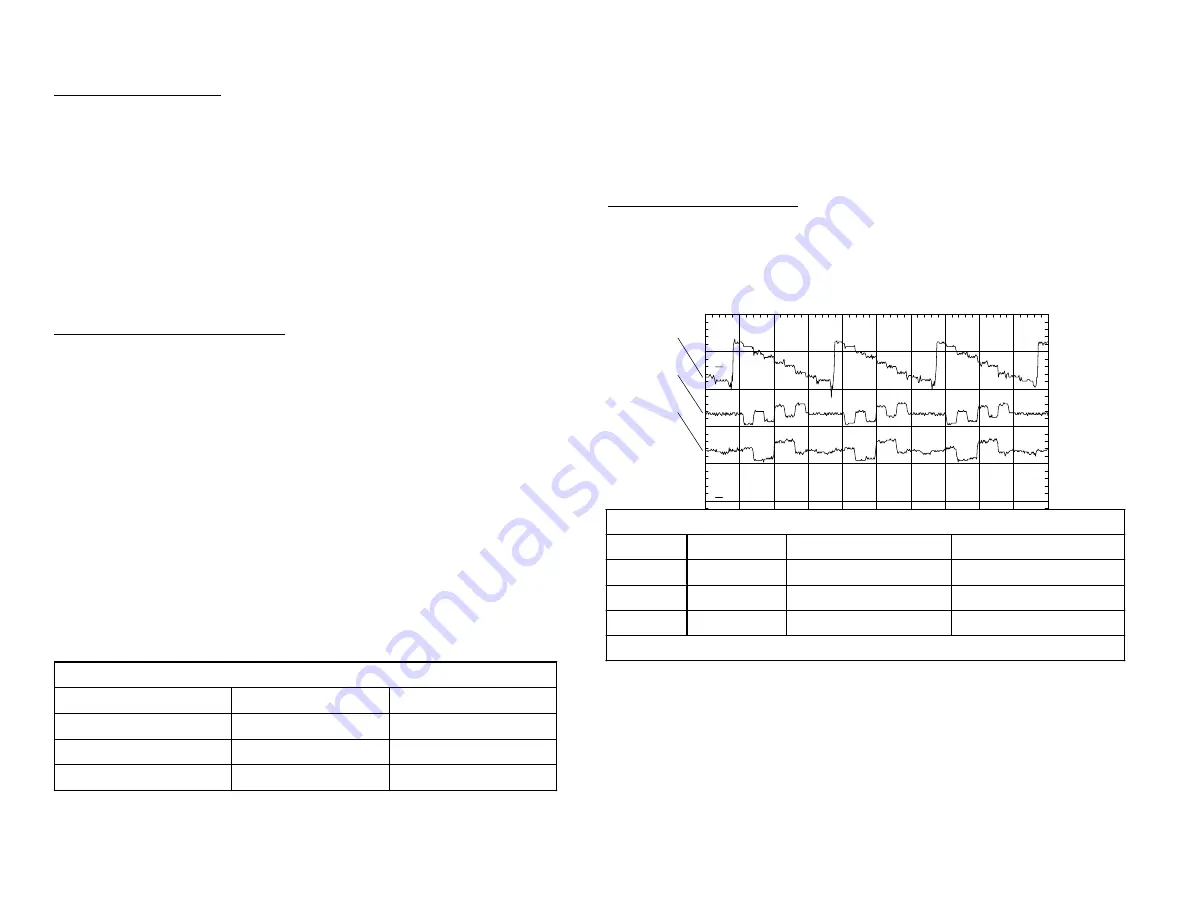
The component video that leaves the B board is shown in the waveform:
Component Video leaving the B board - Color Bar input
Channel
Name
Location
Comments
1
MID Y
CN3203/pin B8
0.7Vp-p
2
MID Cb
CN3203/pin B9
0.7Vp-p
3
MID Cr
CN3203/pin B10
0.7Vp-p
Time base = 10usec/div
The following waveforms show the horizontal sync compared to the Y
signal. After the MID circuit, the frequency is 33.75lkHz.
P M 3 3 9 4 , F L U K E & P H I L IP S
c h 3
c h 2
c h 1
1
2
Содержание KV-32XBR400
Страница 1: ......
Страница 5: ...1 NOTES ...
Страница 12: ...8 NOTES ...
Страница 14: ...10 NOTES ...
Страница 83: ...APPENDIX ...

