43
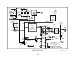
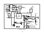
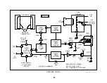
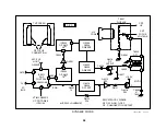
HV Converter Block
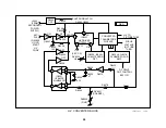
This HV Converter is similar to the two low voltage power supplies be-
cause they have the same MCZ3001D ICs. This power supply differs
only in the start up, voltage output, and over voltage (OV) protection. The
Flyback Output transformer of this power supply generates regulated
31.5kV and focus voltage for the CRT. Excessive current drawn by this
stage will permit Q8009 to shut down the TV set, but there will be no
Standby light blink indication.
Start Up
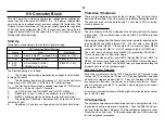
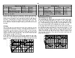
Three items are necessary to start this HV power supply:
HV Converter Inputs (Starting)
Name
From
Destination
1. +200V
D6515 & D6517 / cathode(D Bd)
IC8002/18 (199V)
2. +15V
D6514 / cathode (D Bd)
IC8002/8 (14.7V)
3. AFC-
PLS
H Out Q5030/C (D Bd)
(CN5501/pin 3 = 9Vp-p
IC8002/1 (1.6V)
The Start sequence is as follows:
1.
The Primary power supply produces low voltages for the Horizon-
tal stage (D board).
2.
The Secondary power supply pr135V for the Horizontal
stage, along with +200V and +15V for this HV Converter stage.
3.
The Horizontal Output stage is needed to develop AFC-PLS pulses
(CN5501/pin 3 = 9Vp-p) for the HV Converter.
4.
AFC-PLS pulses turn ON Q8001 and turn OFF Q8002.
5.
IC8002/pin 1 rises. (1.3Vdc is the minimum to start IC8002).
6.
IC8002’s oscillator starts and drives the flyback transformer.
7.
The voltage at IC8002/pin 2 decreases from 4V to 2Vdc as the HV
climbs to 31.5kV.
8.
Regulated HV and focus voltage output the Flyback transformer.
Protection / Shutdown
There are two protection circuits for the HV stage. The first circuit shuts
down the HV oscillator if the HV is excessive (without affecting the sound).
The second circuit shuts down the entire TV set if the +200V current de-
mand is excessive.
Excessive HV Protection
The HV oscillator in IC8002 is stopped if the HV sampled from the flyback
is excessive. The oscillator stops when via Q8003 or Q8004 grounds
IC8002/pin 1.
Sample high voltage from the flyback transformer normally takes two paths
to keep Q8003 and Q8004 turned OFF. The first path is from D8014
through 33V zener D8025. If the sample HV is excessive, zener D8025
conducts, turning ON Q8010. A LOW voltage outputs to IC8001/pin 7.
The LOW input and output turns Q8003 ON, grounding IC8002/pin 1.
This shuts down the HV Converter stage.
The second shutdown path is from D8014 through R8078, and IC8001 to
Q8004. An excessive voltage will similarly turn Q8004 ON, shutting down
the HV Converter. RV8001 and RV8003 form a voltage divider along the
feedback path to set the shutdown point.
Excessive Current Protection
Excessive current drawn by the +200V line into this HV Converter stage
causes the TV to shut down. There is NO Standby light blink indication
when this HV stage shuts down the TV. The +200 line feeds IC8002, the
two converter transistors (not shown), and flyback transformer. Exces-
sive HV will also cause the TV to shut down by drawing too much current
through the flyback.
In summary, shutdown without a Standby light indication indicates a prob-
lem in this HV stage.
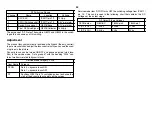
HV Adjustment
The adjustment procedure for these three controls is straightforward. First
the shutdown controls are preset (ineffective). Then the RV8002 HV con-
trol is set to the shutdown trip point. The two shutdown controls are reset.
Finally the HV control is set. A HV probe connected to a DVM is required
for this adjustment procedure.
Содержание KV-32XBR400
Страница 1: ......
Страница 5: ...1 NOTES ...
Страница 12: ...8 NOTES ...
Страница 14: ...10 NOTES ...
Страница 83: ...APPENDIX ...

