63
ch2
ch1
CH1 2.00 V=
CH2 2.00 V= MTB5.00ms- 1.32dv H xx
1
2
T
Picture Tilt Correction
When flat screen picture tubes were first manufactured, lines that were
not straight were very noticeable. This meant additional pincushion and
convergence circuitry was required to improve the picture quality.
If the yoke were a little off center, the slight tilt of the picture would also be
noticeable. A picture tilt circuit was added to Sony
flat screen Wega
TVs to correct for this tilt. The user can perform Tilt Correction from the
setup menu. The coarse adjustment is performed in the service mode by
changing the data in category 2150D, item 6 (NSCO).
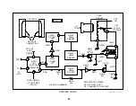
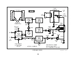
The circuit required a DC voltage to be applied to a N/S coil suspended
about the perimeter of the yoke housing at the bell of the tube. Applying
a voltage to this N/S coil produces a magnetic field. The field offsets the
three beams as they emerged from the electron gun structure, rotating
the picture.
A sawtooth waveform is also added to this DC voltage for horizontal trap-
ezoid correction. Therefore, there is a DC voltage and a sawtooth signal
present at the coil. Both the DC level and sawtooth amplitude can be
controlled in the service mode.
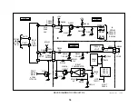
Tilt Correction Circuit
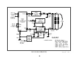
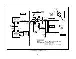
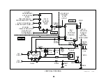
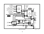
The tilt correction DC voltage and the horizontal trapezoid correction
sawtooth signal are created by IC201. The signal and DC voltage leave
IC201/pin 51 and are amplified by IC5510 before being sent to the N/S
coil. The voltages in normal operation and when the user has set the tilt
to both extremes (+7) are shown in the chart.
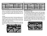
Tilt correction Voltages
Location
Name
0 rotation
-7 rotation
+7 rotation
CN201/pin 5
Output of IC201
4Vdc
5Vdc
3Vdc
CN9102/pin
12
N/S coil
0V
-4.8Vdc
5Vdc
Horizontal Trapezoid Correction Circuit
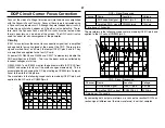
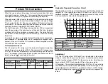
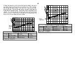
The trapezoid correction signal takes the same path the tilt correction DC
voltage did. This signal comes from IC201/pin 51 as a 60 Hz 0.3Vp-p
sawtooth waveform. IC5510 brings the signal level up to 2Vp-p for the
main sawtooth plus 4Vp-p for the low going spike.
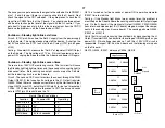
Horizontal Trapezoid Correction Waveform
Channel
Name
Location
Voltage
1
V Saw 1
CN201/pin 5
0.3Vp-p
2
N/S Coil
CN5509/pin 12
6Vp-p
Time base = 5msec/div.
Adjustment
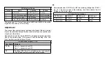
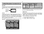
Tilt - The DC voltage from IC201/pin 51 can be adjusted in the service
mode, as well as from the user’s setup menu. Access the coarse adjust-
ment by locating category 2150D-1 in the service mode. Scroll down to
item number 6 - NSCO to change the tilt from the service mode.
H Trapezoid - The sawtooth amplitude from IC201/pin 51 can also be
controlled from the service mode, independent of the DC voltage. In the
same category as for tilt (2150D-1), scroll down to item 7 - HTPZ. Chang-
ing its data changes the signal amplitude and corrects for trapezoid dis-
tortion.
Содержание KV-32XBR400
Страница 1: ......
Страница 5: ...1 NOTES ...
Страница 12: ...8 NOTES ...
Страница 14: ...10 NOTES ...
Страница 83: ...APPENDIX ...


