49
PM3394, FL UK E & PHILIPS
c h3
c h2
c h1
CH1! 5.00 V=
CH2! 5.00 V=
CH3! 5.00 V= CHP MTB5.00m s- 2.58d v c h 1-
1
2
3
T
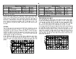
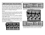
Memory Communications during picture Tilt
Scope Channel
Name
Location
Voltage
1
WP (read/write)
CN702/pin 8
5Vp-p
2
Clock
CN703/pin 1
5Vp-p
3
Data
CN703/pin 2
5Vp-p
Time base = 5msec/div.
Although not shown, network 0 data and clock are accessible at the 10-
pin rear panel service connector.
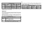
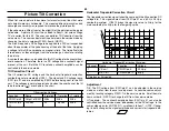
Network 1 communications is also always present when the TV is ON. A
scope shot of the two 5Vp-p signals is shown:
ch2
ch1
CH1 5.00 V~ STOP
CH2 5.00 V= MTB5.00ms- 1.32dv H xx
1
2
T
Network 1 Communications - TV Channel 7 displayed
Scope Channel
Name
Location
Voltage
1
Clock
CN706/pin 7
5Vp-p
2
Data
CN706/pin 8
5Vp-p
Time base = 5msec/div.
Communications Network 2
Communications network 2 is only used between three ICs on the B board.
MID uCom IC3090 communicates with MID IC3408 to retrieve processed
data such as the input horizontal frequency and uses it to select video
signal paths.
MID uCom IC3090 also communicates with memory IC3089 and IC3408
to set up the twin picture (picture with picture) parameters. This data in
memory IC3089 is accessed in the service mode using MID uCom IC3090
to interface to IC701. MID uCom IC3090 is connected to communica-
tions network 1 and 2.
Содержание KV-32XBR400
Страница 1: ......
Страница 5: ...1 NOTES ...
Страница 12: ...8 NOTES ...
Страница 14: ...10 NOTES ...
Страница 83: ...APPENDIX ...

