


– 9 –
KP-FX43M31/M61/M91
KP-FX53M31/M61/M91
RM-998
SECTION 2
DISASSEMBLY
2-1. REAR COVER REMOVAL
(1) KP-FX43
(2) KP-FX53
2-2. MAIN BRACKET REMOVAL
2-3. SERVICE POSITION
2
COVERS
Cut them off with a plier or the like from
chassis assembly in case of checking
printed circuit boards.
After checking, turn over the covers and
secure them with screws.
(screws 7-685-648-79 -BVTP 3X12)
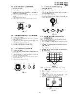
1
Eleven screws
(Hexagon head)
2
Rear board
1
Eleven screws
(Hexagon head)
2
Rear board
3
Main bracket section
1
Optical shield
2
Two screws
(tapping screw
hexagon head)
1
Main bracket section
2
Eight screws
(BVTP 3X12)


