– 56 –
KP-FX43M31/M61/M91
KP-FX53M31/M61/M91
RM-998
SECTION 4
SAFETY RELATED ADJUSTMENT
4-1. HV
REGULATION
ADJUSTMENT
When replacing the following components marked with
]
on the schematic diagram, always check hold-down volt-
age and if necessary re-adjust.
HV REGULATION ADJUSTMENT
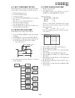
1. Connect a HV static voltmeter to the unconnected plug
of the highvoltage block. (Fig.4-1)
2. Power on the set.
3. Confirm that the static voltmeter reading is
31.0 ± 0.2 kV.
4. If not, adjust with VR8001 to the specified value.
5. After adjustment, apply sufficient amound of RTV
KE490 on the VR8001. (Fig.4- 2)
HV HOLD-DOWN ADJUSTMENT
1. Connect a HV static voltmeter to the unconnected plug
of the highvoltage block. (Fig.4- 1)
2. Power on the set.
3. Connect an external 10k VR at CN8015 and adjust
this VR so that the high voltage is 34.50 kV.
4. Confirm that the static voltmeterreading is
34.5 ± 0.4 kV.
5. If not, adjust with VR8002 to the specified value.
6. After adjustment, put the VR cover on VR8001 as
shown below and apply sufficient amound of RTV
KE490 on the VR8002. (Fig.4- 2)
4-2. HV HOLD-DOWN ADJUSTMENT
When replacing the following components marked with
]
on the schematic diagram, always check hold-down volt-
age and if necessary re-adjust.
[
: VR8001
]
: C8054, C8086, C8088, C8100, C8104, C8118,
C8123, C8124
D8019, D8020, D8022, D8028, D8036
IC8008
Q8035, Q8043
R8043, R8159, R8166, R8171, R8196, R8201
T8004(LOT), T8005(FBT)
HV block, D board
[
: VR8002
]
: C8079, C8083, C8090, C8129
D8013, D8015, D8038, D8043, D8051
IC8006
Q8021
R8055, R8102, R8128, R8129, R8131, R8139,
R8140, R8142, R8153, R8163, R8223, R8230
T8004(LOT), T8005(FBT)
HV block, D board
4-3.+B MAX VOLTAGE CONFIRMATION
The following adjustments should always be performed
when replacing IC6503.
1. Supply 220V AC to variable autotransformer.
2. Receive dot signal pattern and set the PICTURE and
BRIGHTNESS setting to their minimum.
3. Confirm the voltage of TP+B 135V is less than 137.0
Vdc.
4. If step 4 not satisfied, replace IC6503 and repeat above
steps.
4-4.+B OVP CONFIRMATION
1. Add to low voltage power supply between to TP6502
and 4 pin of IC6502.
2. Supply 220V AC to variable autotransformer.
3. Power on the Set and receive dot signal pattern.
4. Set the PICTURE and BRIGHTNESS settings.
5. Check the OVP is actived.
Operate : power supply voltage 2.70 ± 0.05 V
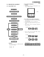
Fig. 4-1
RTV KE490
VR8001, VR8002
Fig. 4-2
Remove the cap off
from the unused
terminal and connect a
HV static voltmeter
there.

