12
Overview
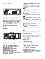
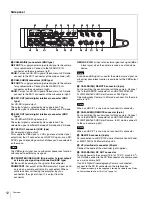
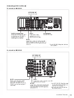
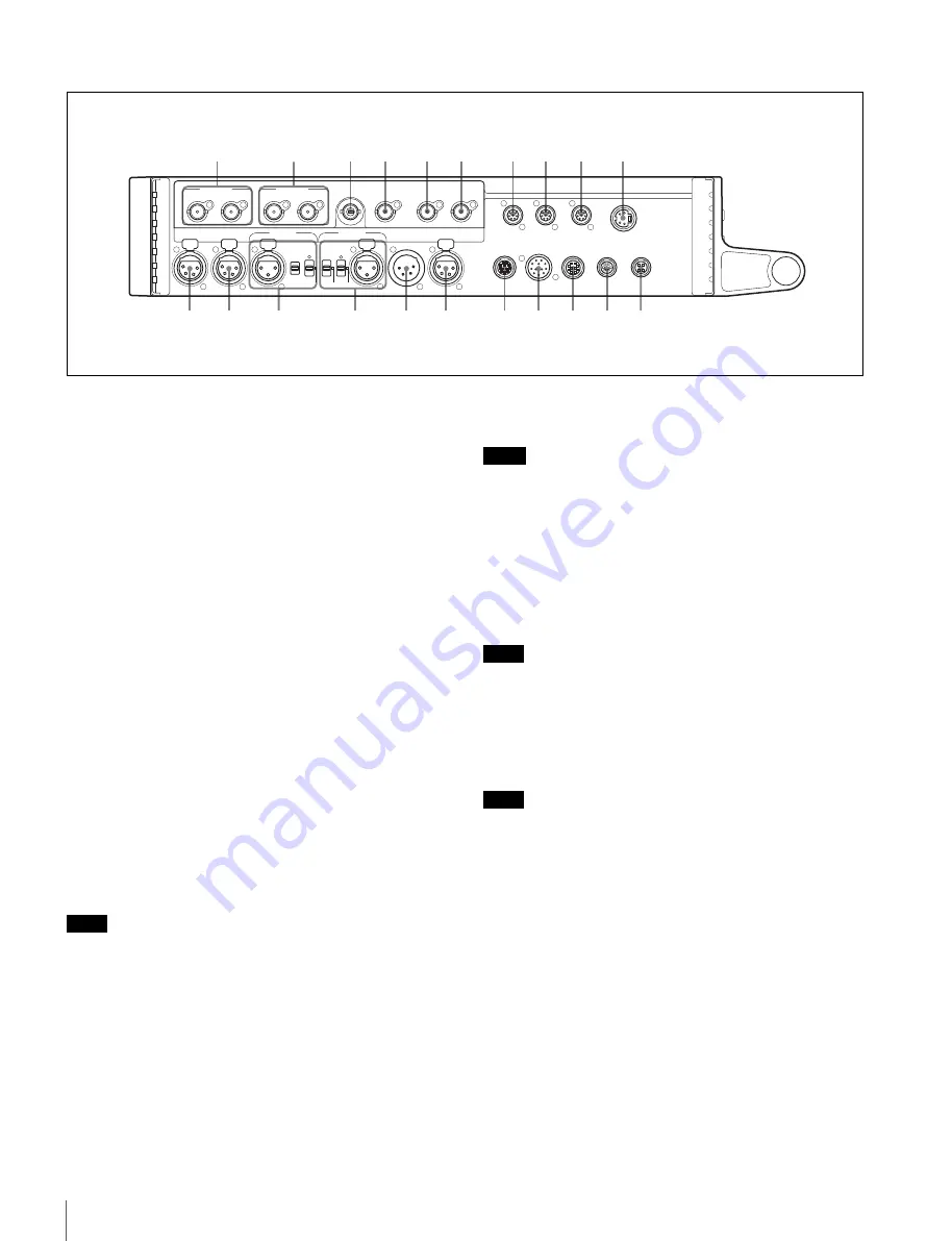
Side panel
a
CAM-MAIN(L) connectors (BNC type)
REF OUT:
To supply an external gen-lock signal to the camera
for synchronization. Connect to the GENLOCK IN
connector on the main camera (left).
SDI IN:
To input an HD-SDI signal of the camera. In 3D mode,
connect to the SDI 1 connector of the main camera (left).
b
CAM-SUB(R) connectors (BNC type)
REF OUT:
To supply an external gen-lock signal to the camera
for synchronization. Connect to the GENLOCK IN
connector on the sub camera (right).
SDI IN:
To input an HD-SDI signal of the camera. In 3D mode,
connect to the SDI 1 connector of the sub camera (right).
c
SDI1 OUT (serial digital interface) connector (BNC
type)
For HD-SDI signal output.
The output signal is selected by menu operation. The
selectable signal is different between 2D mode and 3D mode.
d
SDI2 OUT (serial digital interface) connector (BNC
type)
For HD-SDI or SD-SDI signal output.
The output signal is selected by menu operation. The
selectable signal is different between 2D mode and 3D mode.
e
TEST OUT connector (BNC type)
For an analog signal output.
This supplies a VBS signal, an HD signal equal to the signal
output from the VF connector, an HD-SYNC signal, or an SD-
SYNC signal, depending on which of these you have selected
on the menu.
The VBS output signal has no subcarrier phase-lock function
with respect to external sync signals.
f
PROMPTER1/GENLOCK IN (prompter 1 signal output/
external sync signal input) connector (BNC type)
Set the switch according to the signal at the connector.
PROMPTER1:
For output of the VBS prompter 1 signal (valid
only when a camera control unit is connected). When a
camera control unit having two prompter inputs is
connected, the signal of input 1 is output from this
connector.
GENLOCK IN:
For input of an external gen-lock signal (BB or
3-level sync) when the camera is used as a standalone
device.
Even when a BB signal is used for the external sync signal, no
subcarrier phase-lock function is available for the VBS output
signal.
g
CAM-MAIN(L) REMOTE connector (8-pin)
For transmitting the control signal with the camera. Connect
this to the REMOTE connector of an HDC1500R/1600R/
1400R/1500/1600 HD Color Camera or F35 Digital
Cinematography Camera. In 3D mode, connect it to the main
camera (left).
When an HDC-P1 is used, do not connect this connector.
h
CAM-SUB(R) REMOTE connector (8-pin)
For transmitting the control signal with the camera. Connect
this to the REMOTE connector of an HDC1500R/1600R/
1400R/1500/1600 HD Color Camera. In 3D mode, connect it
to the sub camera (right).
When an HDC-P1 is used, do not connect this connector.
i
REMOTE connector (8-pin)
For connection to an RCP-1000-series Remote Control Panel,
or MSU-1000/1500 Master Setup Unit.
j
VF (viewfinder) connector (20-pin)
Connect the cable of the viewfinder (not supplied).
k
CAM-MAIN(L) DC OUT connector
To supply power to the camera (10.5 to 17 V DC, max 5.5 A
1)
).
In 3D mode, connect to the DC IN connector of a camera used
as a main camera (left).
If an F35 Digital Cinematography Camera is connected,
connect to the DC IN connector on the interface box.
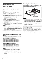
1) The power capacity to be supplied is limited. For details see
on Power Supplied from This Unit” (page 14)
1
2
3
4
5
6
7
8
9
0
wa
w;
ql
qk
qj
qh
qg
qs
qa
qf
qd
CAM-MAIN(L)
REF OUT
SDI IN
CAM-SUB(R)
SDI1 OUT
SDI2 OUT
TEST OUT
AUX
CRANE
TRACKER
RET CTRL
DC OUT
0.5A max
DC OUT
4A max
CAM-SUB(R)
DC OUT
CAM-MAIN(L)
DC OUT
DC IN
AUDIO IN 2
AUDIO IN 1
PROMPTER1/
GENLOCK IN
CAM-MAIN(L)
REMOTE
CAM-SUB(R)
REMOTE
REMOTE
VF
REF OUT
SDI IN
MIC
MIC
LINE
OFF
+48V
AES/EBU
LINE
OFF
+48V
Note
Note
Note
Note


