

7
Overview
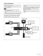
System Configuration
System configurations using peripherals and related devices
are shown in the figures below.
The PLD and software versions installed with the devices to be
used should be updated.
• Make the adjustments required for shooting with the
cameras before connection.
• For 3D operation, be sure to use two cameras of the same
model.
• In 3D mode, the left camera functions as the main camera.
Adjusted values registered for the left camera take priority.
The right camera follows the left camera other than for offset
setting items.
• Production of some of the peripherals and related devices
shown in the figures might be discontinued. For advice on
choosing devices, please contact your Sony dealer or a
Sony sales representative.
• Power capacity supplied from the DC OUT connectors is
limited.
For details, see “Notes on Power Supplied from This Unit”
(page 14).
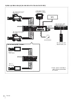
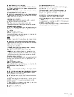
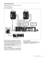
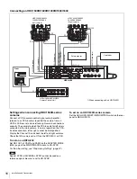
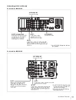
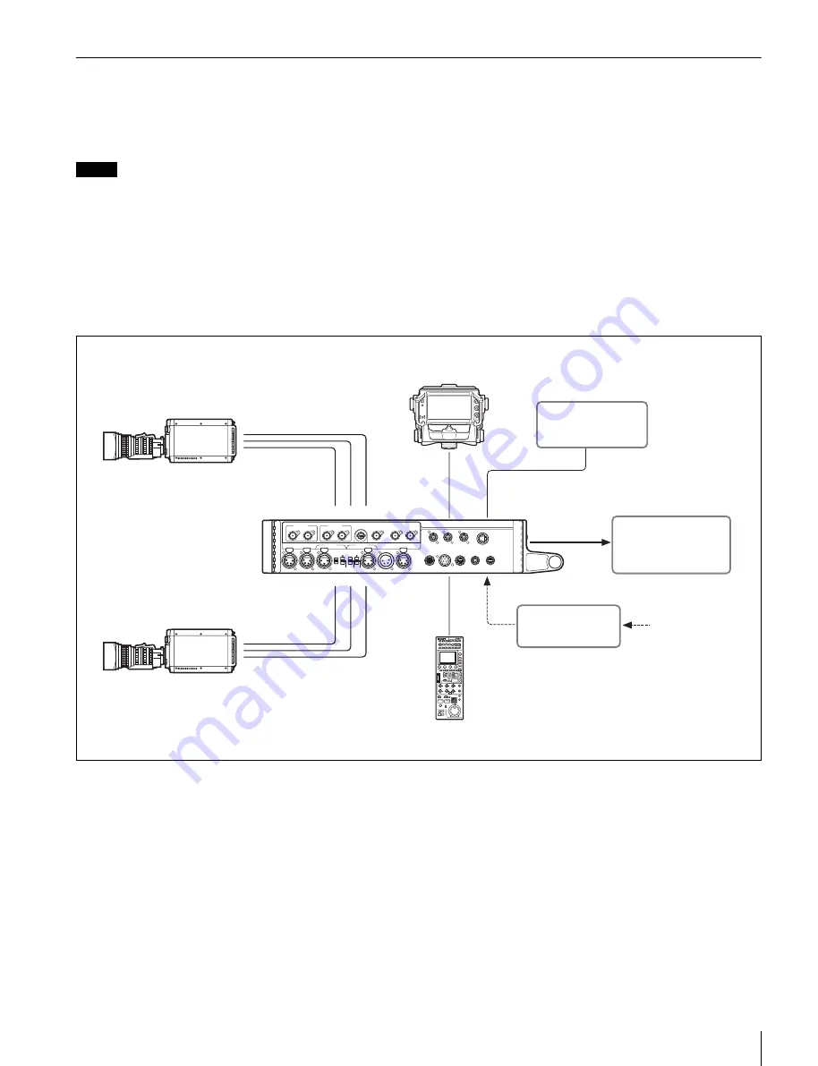
3D multicamera system operation example
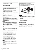
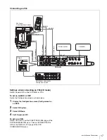
Standalone operation example (two cameras)
Notes
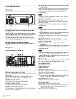
CAM-MAIN(L)
REF OUT
SDI IN
CAM-SUB(R)
SDI1 OUT
SDI2 OUT
TEST OUT
AUX
CRANE
TRACKER
RET CTRL
DC OUT
0.5A max
DC OUT
4A max
CAM-SUB(R)
DC OUT
CAM-MAIN(L)
DC OUT
DC IN
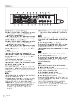
AUDIO IN 2
AUDIO IN 1
PROMPTER1/
GENLOCK IN
CAM-MAIN(L)
REMOTE
CAM-SUB(R)
REMOTE
REMOTE
VF
REF OUT
SDI IN
MIC
MIC
LINE
OFF
+48V
AES/EBU
LINE
OFF
+48V
DC OUT
REF OUT
SDI IN
DC OUT
REF OUT
SDI IN
DC IN
SDI1 OUT
CAM-SUB(R)
CAM-MAIN(L)
VF
SDI2 OUT
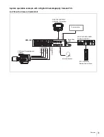
RCP-1500/1501/1530
Remote Control Panel
HDVF-C950W/C730W/
C550W/EL75 Viewfinder
HDFA-200
Picture monitor
AC Adaptor
AC-DN10/DN2B
AC power
SR recorder
HDC-P1
(Right camera)
HDC-P1
(Left camera)


