13
Overview
l
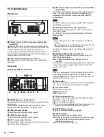
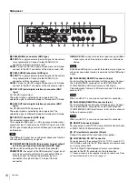
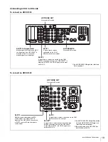
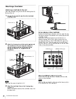
CAM-SUB(R) DC OUT connector
To supply power to the camera (10.5 to 17 V DC, 5.5 A
1)
max.).
In 3D mode, connect to. the DC IN connector of a camera used
as a sub camera (right).
1) The power capacity to be supplied is limited. For details see
on Power Supplied from This Unit” (page 14)
.
m
AUDIO IN 1 connector (XLR 3-pin) and select switches
Connect a channel 1 audio signal and set the switch according
to the connected source device.
Audio input select switch
Set to the appropriate position according to the equipment
connected to the AUDIO IN 1 connector.
MIC:
When an external microphone is connected
LINE:
When a line-level (0 dBu) signal source is connected
Microphone power switches
When a microphone is connected to the corresponding AUDIO
IN 1 connector, set whether or not to supply a power to the
microphone.
OFF:
Not to supply a power
+48V:
To supply a power of +48 V
(No function has been assigned to the uppermost
position. No
power is supplied to the microphone.)
To supply a power of +12 V, consult your Sony representative.
n
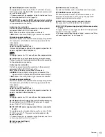
AUDIO IN 2 connector (XLR 3-pin) and select switch
Connect a channel 2 audio signal and set the switch according
to the connected source device.
Audio input select switch
Set to the appropriate position according to the equipment
connected to the AUDIO IN 2 connector.
MIC:
When an external microphone is connected
AES/EBU:
When a digital audio signal is connected (The
signal must be in synchronization with the camera output).
LINE:
When a line-level (0 dBu) signal source is connected
Microphone power switches
When a microphone is connected to the corresponding AUDIO
IN 2 connector, set whether or not to supply a power to the
microphone.
OFF:
Not to supply a power
+48V:
To supply a power of +48 V
(No function has been assigned to the uppermost position. No
power is supplied to the microphone.)
To supply a power of +12 V, consult your Sony representative.
o
DC IN (DC power supply input) connector (XLR 4-pin)
For connection to an AC-DN10 AC Adaptor, etc. to supply
power (10.5 to 17 V DC) to the unit.
p
DC OUT (DC power supply output) 4A max connector
(4-pin)
To supply power to an external device such as a lens (10.5 to
17 V DC, max. 4 A
2)
). The output current depends on the
device to be used.
2) The power capacity to be supplied is limited. For details, see
on Power Supplied from This Unit” (page 14)
.
q
AUX connector (12-pin)
For the future use.
r
CRANE connector (12-pin)
For external interface, such as viewfinder and trunk signal.
s
TRACKER connector (10-pin)
For communication a camera operator and tracker, and
transmission of Intercom 1 and 2. An up tally signal and
program audio signal are also output.
t
RET CTRL (return control) connector (6-pin)
For connection to a CAC-6 Return Video Selector.
u
DC OUT (DC power supply output) 0.5A max connector
(4-pin)
To supply power to a script light of a BKP-7911 Script Holder
(10.5 to 17 V DC, max. 0.5A
3)
).
3) The power capacity to be supplied is limited. For details, see
on Power Supplied from This Unit” (page 14)
.
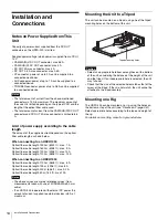
Note
Note


