1-8
Recording
Chapter
2 Pla
ybac
k
and Recording
34
(GB)
Chapter 2
Playback and Recording
Recording
This section describes the necessary connections, settings and operations
to perform recording on this unit. The same settings and operations apply
whether you are using the unit for dubbing or as a stand-alone recorder.
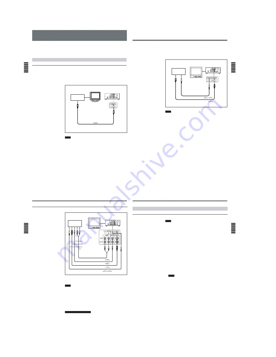
Connections for Recording
To equipment with a DV jack
Connecting to a computer
The video and audio signals are sent from a computer with virtually no
deterioration in quality, enabling high-quality downloading. The signal
flow is automatically detected so you do not need to make separate
connections for input and output.
Notes
• With the DV connection, data codes (recording date/time, camera data)
are transmitted from the computer (player). However, the contents of the
cassette memory are not transmitted.
• If no picture appears via the DV jack, disconnect, then reconnect the
i.LINK cable (DV cable).
Player
Recorder
Computer
Monitor
DSR-11
to the
DV jack
i.LINK cable (DV cable) (not supplied)
l
: Signal flow
Chapter 2
Pla
ybac
k
and Recording
Chapter 2
Playback and Recording
35
(GB)
Connecting to another VCR
The video and audio signals are sent from another VCR with virtually no
deterioration in quality, enabling high-quality recording. The signal flow is
automatically detected so you do not need to make separate connections for
input and output.
Notes
• With the DV connection, the sound is recorded in the same audio
recording mode as that of the source tape. To record in a different audio
recording mode from the source tape, use the analog connection instead.
• With the DV connection, data codes (recording date/time, camera data)
recorded on the source tape are transmitted from the other VCR (player).
As a result, when you play back a recorded tape on this unit and press the
DATA CODE button on the Remote Commander, the same data codes
recorded on the source tape are displayed on the monitor screen.
However, the contents of the cassette memory are not transmitted.
• If no picture appears via the DV jack, disconnect, then reconnect the
i.LINK cable (DV cable).
• As for the LANC connection, see “Notes for the LANC connection” on
the next page.
Player
Recorder
Other VCR
Monitor
DSR-11
to the
DV jack
to the
LANC jack
LANC cable (not supplied)
i.LINK cable (DV cable) (not supplied)
l
: Signal flow
Recording
Chapter
2 Pla
ybac
k
and Recording
36
(GB)
Chapter 2
Playback and Recording
To video equipment without a DV jack
Connect either an S-video cable or a video cable as the cable for video
signals.
Notes
• When recording analog input signals, this unit can digitally output the
signals from the DV IN/OUT connector for backup. Set DV EE OUT on
the VTR SET menu to ON.
For details on the VTR SET menu, see “VTR SET menu” on page 43 (GB).
• When you connect the output jacks of this unit to the input jacks of the
player, select the input correctly with the INPUT SELECT selector on this
unit to prevent a humming noise or distortion of the picture.
• Distorted signals (e.g., when played back at a speed other than normal)
will not be recorded properly.
Notes for the LANC connection
• The LANC connection transmits signals such as control signals, time
code, time counter data, and status data.
• Jacks labeled CONTROL L have the same function as LANC jacks. Jacks
labeled REMOTE may also have the same function.
Player
Recorder
Other VCR
Monitor
DSR-11
to the S-video
output connector
to the video output
jack
to the audio
output jacks
to the LANC jack
Audio cable (not supplied)
Video cable (not supplied)
S-video cable (not supplied)
LANC cable (not supplied)
l
: Signal flow
Chapter 2
Pla
ybac
k
and Recording
Chapter 2
Playback and Recording
37
(GB)
Settings for Recording
Preparation on the recorder (this unit)
Notes
• Before recording, set the date and time on the unit so that the recording
time can be written into the search signal. You can set the date and time
by setting CLOCK SET on the OTHERS menu.
For details on the OTHERS menu, see “OTHERS menu” on page 49 (GB).
• Editing is not possible with a tape that is copyright protected.
1
Power on the video monitor, then set the monitor’s input switch
according to the signals input from this unit.
2
Set up the player to play back a tape.
For details, refer to the instruction manual of the player.
3
When the player is connected to the INPUT jacks on this unit, set the
NTSC/PAL select switch on this unit to the appropriate position
according to the input signals.
For NTSC formatted signals, set the switch to NTSC and for PAL
formatted signals, set it to PAL.
For details on the NTSC/PAL select switch setting, see “Rear Panel” on page
12 (GB).
Notes
• Do not change the NTSC/PAL select switch setting during recording.
• If the color system of the input signals is different from that of the
switch setting, both picture and sound will be muted.
• You do not need to set the NTSC/PAL select switch when inputting
the signals to the DV IN/OUT connector. The unit detects the color
system of the input signal automatically. However when the NTSC/
PAL select switch is set to PAL, the time code generated by the unit
while recording in DVCAM format turns to the non-drop frame mode.
Even if an NTSC formatted signal is input from the DV IN/OUT
connector, the time code generated by the unit is non-drop frame
mode regardless of the TC FORMAT setting on the OTHERS menu.
If you intend to set the unit to generate the time code in the drop
frame mode, set the switch to NTSC.
4
Power on this unit by pressing the ON/STANDBY switch on this unit.
(Continued)


