background image

Chapter 4

Menus

56

Chapter 4

Menus

CAMERA menu

Menu item

Settings

SHUTTER

Set the camera shutter speed (in seconds)

4, 2, 1, 1/2, 1/3, 1/4, 1/6, 1/12, 1/25, 1/50, 1/60, 1/125, 1/250,
1/500, 1/1000, 1/2000, 1/5000, 1/10000
Factory default setting: 1/125

EXPOSURE

Set the ISO exposure index for the camera

ISO 20, 40, 80, 160
Factory default setting: ISO 20

INCREMENT

Select whether the memory selection is incremented
automatically or not.
For details of the method of memory selection, see page
37.

ON: The memory selection is incremented automatically.

When this setting is selected, the menu items “•REVIEW
TIME”, “•IRIS OPEN”, and “•LOOP” appear.

OFF: The memory selection is not incremented automatically.
Factory default setting: ON

•REVIEW TIME

When the above “INCREMENT” item is set to “ON,”
adjust the review time, during which an image captured to
memory is displayed after the release button is pressed.

0 sec, 1 sec, 3 sec, 5 sec, 10 sec
Factory default setting: 3 sec

•IRIS OPEN

When the above “INCREMENT” item is set to “ON,”
select whether after the release button is pressed to
return to the live monitor mode, or not (i.e. to return the
lens iris to the fully open position)

ON: Return to the live monitor mode.  Use this setting when

you wish to check each new image on the monitor screen.

OFF: Do not return to the live monitor mode (keep the iris

setting unchanged).  Use this setting when the timing of
image capture is important.

Factory default setting: ON

•LOOP

When the above “INCREMENT” item is set to “ON,”
select whether or not to use the memory loop mode.
For details, see page 38.

ON: Select the memory loop mode.  After capturing an image

to memory 9, memory 1 is automatically selected for the
next image.

OFF: Do not select the memory loop mode.  After capturing an

image to memory 9, the message “MEMORY FULL”
appears.

Factory default setting: ON

ROTATE

Select whether or not to rotate the menu and status
displays on the monitor screen through 90 degrees.

ON: Rotate the displays through 90 degrees.  Use this setting

to make it easier to check the displays in portrait format.

OFF: Do not rotate the displays through 90 degrees.  Use this

setting to make it easier to check the displays in landscape
format.

Factory default setting: ON

AE MODE

Select the manual or automatic exposure mode.

MANUAL: Manual adjustment
APERTURE: Aperture priority automatic exposure
SHUTTER: Shutter priority automatic exposure
PROGRAM: Program automatic exposure
Factory default setting: MANUAL
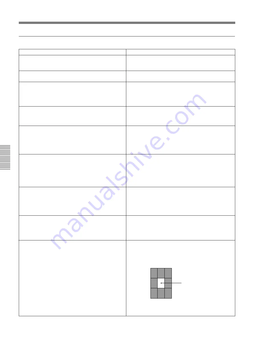
METERING

Select the exposure metering method in the live monitor
mode.

PEAK: Adjust exposure to the maximum intensity “cell of

image” as defined by dividing the whole image into nine
cells having the same area. (The illustration below shows
a case in which the maximum intensity cell is the central
cell.)  With this setting the surroundings of highlights may
become dark.

AVG: Adjust exposure to the average intensity of the image.

With this setting there may be “burn-out” in the highlights.

Factory default setting: PEAK

Menu Settings

Maximum intensity
“cell of image”

Содержание DKC-ST5

Страница 1: ... 1997 by Sony Corporation Operating Instructions Before operating this unit please read this manual thoroughly and retain it for future reference Digital Photo Camera 3 859 629 13 1 DKC ST5 ...

Страница 2: ... comply with the limits for a digital device pursuant to Subpart B of Part 15 of FCC Rules Important Notice Thank you for choosing the Sony DKC ST5 Digital Photo Camera referred to below as the product The DKC ST5 control software referred to below as the software is included with the product as sample software in order to enable you to utilize the full potential of the product The software is pro...

Страница 3: ...nd Memory Monitor Modes 22 Status Indications 23 Image Adjustments and Focusing 24 Adjusting the Zoom 24 Focusing 24 Adjusting the Black Balance 26 Adjusting the White Balance 27 Adjusting the Iris 30 Using the AE Function 31 Shooting 35 Basic Procedure 35 Selecting a Memory 37 Reviewing a Captured Image 42 Switching Between Landscape and Portrait Orientations 43 About This Manual 5 Chapter 3 Inst...

Страница 4: ...hapter 5 Using the Control Software Overview 59 Required Hardware 59 Required Software 59 Installinzg the Control Software 60 Preparations 60 Installing the Control Software 60 Using the Control Software 61 Uninstalling the Control Software 61 Chapter 6 Maintenance Error Messages 63 Troubleshooting 64 Appendix Notes on Use 65 Specifications 66 ...

Страница 5: ...troller Using the supplied control software By installing the DKC ST5 Control Software supplied with the product on 3 5 inch floppy disks you can control the DKC ST5 from a computer For details of the operation of the software read the Readme files installed with the control software For details of the installation of the control software see Chapter 5 of this manual About This Manual ...

Страница 6: ......

Страница 7: ...e captured into memory consecutively at about 1 second intervals After checking captured images on a monitor you can select the images for transfer to a computer Flexible color gradation representation The A D conversion uses a 10 bit lookup table which makes for flexible color gradation representation Optimized dynamic range Gamma correction and knee point adjustment allow the dynamic range to be...

Страница 8: ...nts required in addition to the standard product configuration see the section Principal Examples of Use on the next page System Features Digital processing unit Camera head Remote controller Camera cable AC cord Four 3 5 inch floppy disks containing the Control Software The following items are also supplied as standard accessories Type C 2 for PAL model only Ferrite cores Type A 2 Type B 2 for NT...

Страница 9: ... can build an instant portrait system as shown below You can capture a number of images into memory review them on the monitor then print a selected image Flash Generator Remote controller Viewfinder Camera head Lens VCL 1205BYS Camera Cable 10 m supplied Monitor Digital processing unit Computer SCSI cable SCSI cable UP D8800 Note Do not connect or disconnect the cables when any system component i...

Страница 10: ...ote controller Camera head Lens VCL 1205BYS Camera Cable 10 m supplied Monitor Digital processing unit Computer SCSI cable Notes Do not connect or disconnect the cables when any system component is powered on When you use the camera in such a system configuration as illustrated select CAMERA in the main menu and set the ROTATE item to OFF For details of menu operations see Chapter 4 ...

Страница 11: ...BYS you can fit any 2 3 inch 48 mm bayonet mount lens 2 Lens locking lever This locks the lens as described under 1 Lens mount 3 LENS2 connector 12 pin female When using a lens other than the special purpose one VCL 1205BYS connect the cable from the lens to this connector 4 Mounting hole This accepts the fixing screw when the camera head is mounted on a tripod 1 Lens mount 3 LENS2 connector 4 Mou...

Страница 12: ...or X contact socket Connect the cable from a flash unit This connector is not used when the cable from the flash unit is connected to the FLASH connector on the digital processor 4 REMOTE connector 12 pin female Connect the supplied remote controller 5 LENS1 connector 20 pin female When using the special purpose lens VCL 1205BYS connect the cable from the lens 6 PROCESSOR connector 26 pin male Con...

Страница 13: ...the digital processor Press it once more to power off Note Once you have powered off the digital processor do not try to power it on again immediately Doing this may result in failure anyway 2 POWER indicator This lights when the digital processor is powered on POWER ON OFF Ø ø 1 1 POWER switch 2 POWER indicator ...

Страница 14: ...onnections see the section SCSI Connections on page 48 3 FLASH connector X contact socket Connect the cable from a flash unit This connector is not used when the cable from the flash unit is connected to the FLASH connector on the camera head 4 AC IN connector Use the supplied power cord to connect to a 120 V AC NTSC model or 220 to 240 V AC PAL model power outlet 5 CAMERA connector 26 pin female ...

Страница 15: ... cable not supplied connect this to the composite video input connector BNC type of the monitor S VIDEO output connector Mini DIN 4 pin Using an S video cable not supplied connect this to the S video input connector of the monitor R G B and SYNC output connectors BNC type Using 75 ohm coaxial cables not supplied connect these to the RGB and sync input connectors of the monitor ...

Страница 16: ...n the memory monitor mode these buttons select the memory MEMORY Pressing this button switches from the currently selected memory to the next higher numbered memory 1 n 2 n 3 MEMORY Pressing this button switches from the currently selected memory to the next lower numbered memory 9 n 8 n 7 4 FOCUS FAR NEAR buttons These adjust the focus FOCUS FAR Pressing this button focuses further away FOCUS NEA...

Страница 17: ...matically sets up the system according to the settings in the file You can also use this button to switch from one user file to another For details of the Control Software see Chapter 5 7 E ZOOM electronic zoom button Pressing this button zooms in at a 2 1 ratio on the center of the live image E ZOOM mode Use this button to focus quickly Pressing the button once more exits the E ZOOM mode and retu...

Страница 18: ...current setting For details of the procedure for white balance adjustment see page 27 WB white balance LIVE button Hold this button down for at least two seconds to adjust the white balance for the live image output This carries out the white balance adjustment automatically with the lens iris in the fully open position For details of the procedure for white balance adjustment see page 27 BB black...

Страница 19: ...f a frame showing the effective print area horizontal and vertical coordinate axes and a background image The factory default setting is for this display function to be disabled For details of the control software see Chapter 5 CHARACTER ON OFF button Press this button to toggle the status display on the monitor screen between the on and off settings The factory default setting is for the status d...

Страница 20: ......

Страница 21: ...processor emits a double beep about five seconds after it is powered on indicating that it is ready for operation For details of the menus see Chapter 4 When the digital processor is ready for operation the system automatically switches to the live monitor mode and the mode indication LIVE is displayed on the monitor screen For details of the live monitor mode see the section Live and Memory Monit...

Страница 22: ...e and memory monitor modes In the live monitor mode the image from the camera is output to the monitor At this point the lens iris is automatically in the fully open position regardless of the current setting and LIVE appears in the status indication on the monitor in the position indicating the mode In the memory monitor mode the image saved in the memory currently selected with the MEMORY button...

Страница 23: ...tus display is in the on mode it indicates the live or memory monitor mode the iris setting and the memory status selection and availability of each memory Even when the status display is in the off mode the status display appears but disappears again after a few seconds The following illustration shows the positions of the various status indication items Operating mode Iris setting f stop Memory ...

Страница 24: ...cusing Focusing without changing the zoom angle To focus further away press the FOCUS FAR button on the remote controller To focus closer press the FOCUS NEAR button on the remote controller To focus manually set the lens to manual focusing mode and turn the focusing ring Image Adjustments and Focusing STDBY USER LIVE MEMORY E ZOOM IRIS MEMORY FOCUS ZOOM FAR NEAR T W ZOOM T button ZOOM W button ST...

Страница 25: ...he E ZOOM button This switches to the E ZOOM mode and zooms in at a 2 1 ratio on the center of the image 3 Press the FOCUS FAR button or FOCUS NEAR button to adjust the focus 4 Press the E ZOOM button This exits the E ZOOM mode and returns to the normal image Note Until you exit from the E ZOOM mode only the FOCUS FAR NEAR and ZOOM T W buttons operate STDBY USER LIVE MEMORY E ZOOM IRIS MEMORY FOCU...

Страница 26: ... that the lens is in automatic iris mode Note If you are using a lens with no automatic iris function close the iris completely 2 Hold down the BB button on the remote controller for at least two seconds This automatically closes the lens iris completely and carries out black balance adjustment The message Reading Color Table appears on the monitor screen The image on the monitor screen may flicke...

Страница 27: ...ress the MENU button on the remote controller to access the main menu and make the following settings Select the PICTURE menu and set C TEMP to AWB this is the factory default setting Select the FLASH menu and if using a flash set the FLASH item to ON this is the factory default setting Next select the flash interval with the INTERVAL item If not using a flash set the FLASH item to OFF For details...

Страница 28: ...s white balance adjustment The message Reading Color Table appears on the monitor screen If the FLASH menu setting is FLASH ON the flash flashes several times When the adjustment is completed the message WB OK appears If the adjustment was not achieved The message WB NG Please try again appears Repeat the above procedure Adjusting the White Balance ...

Страница 29: ...g position a white subject white pattern white cloth etc and zoom in so that it fills the screen 3 Hold down the WB LIVE button on the remote controller for at least two seconds This automatically starts white balance adjustment The message Reading Color Table appears on the monitor screen When the adjustment is completed the message WB OK appears If the adjustment was not achieved The message WB ...

Страница 30: ...e CHARACTER ON OFF button to switch on the status display The f stop setting appears on the monitor screen 4 To increase the numerical value of the f stop i e to stop down the iris for still image capture press the IRIS button To decrease the numerical value of the f stop i e to open up the iris for still image capture press the IRIS button Note Changing this setting does not affect the iris durin...

Страница 31: ...The aperture priority AE mode automatically adjusts the shutter speed to an iris f stop setting made by the user so that the optimal brightness level is obtained To set the AE function to aperture priority mode use the following procedure 1 Press the MENU button on the remote controller to access the main menu Select the CAMERA menu from the main menu and set AE MODE to APERTURE For details of men...

Страница 32: ...following procedure 1 Press the MENU button on the remote controller to access the main menu and select the CAMERA menu For details of menu operations see Chapter 4 2 In the CAMERA menu set AE MODE to SHUTTER then exit the menu system The f stop indication in the monitor screen changes to AE S Note Setting the AE function to shutter priority mode disables the remote controller s IRIS buttons 1 MEN...

Страница 33: ...ote controller to access the main menu and select the CAMERA menu For details of menu operations see Chapter 4 2 In the CAMERA menu set AE MODE to PROGRAM then exit the menu system The f stop indication in the monitor screen changes to AE P Note Setting the AE function to program mode disables the SHUTTER and ISO items of the CAMERA menu the remote controller s STDBY button when a lens other than ...

Страница 34: ...ompensation setting use the following procedure 1 When the menu system is not accessed press the or button on the remote controller At the bottom of the monitor screen appears the indication AE CMP followed by the currently set AE compensation value 2 To increase or decrease the AE compensation value press the or button on the remote controller The setting range is 9 to 9 1 MENU ENTER WB STILL WB ...

Страница 35: ...on selection and availability 2 Select the memory into which you wish to capture an image For details see the section Selecting a Memory on page 37 Note If you select a memory which already holds an image carrying out step 4 will overwrite this existing image in the memory 3 If in the memory monitor mode press the LIVE MEMORY button to switch to the live monitor mode The LIVE mode indication appea...

Страница 36: ... STAND BY mode indication appears on the monitor screen When the memory selection mode is increment on first the system switches to review mode and the image captured to memory appears on the monitor for a few seconds Next the system switches back to live monitor mode During the review the REVIEW mode indication appears on the monitor screen When the memory selection mode is increment off the syst...

Страница 37: ...ERA menu then set the INCREMENT item to ON this is the factory default setting For details of menu operations see Chapter 4 When using the system initially memory 1 is selected for image capture The white squares indicate that the memories do not hold images 1 1 2 Memory status indication Press release button An image is captured in memory 1 and after a transient review the system returns to the l...

Страница 38: ...i e the status indication shows a film icon for memory 1 when you press the release button this captures a new image to memory 1 and the previously stored image is lost Loop off mode After an image is captured to memory 9 there is no automatic memory selection and after the review the system returns to the live monitor mode with a message MEMORY FULL display To switch between loop on mode and loop...

Страница 39: ... of operation in increment off mode When using the system initially memory 1 is selected for image capture 1 1 1 3 3 Memory status indication Switch to live monitor mode and press release button An image is captured in memory 1 and the system automatically switches to memory monitor mode Memory 1 remains selected Switch to live monitor mode and press release button A new image overwrites the exist...

Страница 40: ...apter 2 Operation 40 Chapter 2 Operation To select the increment off mode From the main menu select the CAMERA menu then set the INCREMENT item to OFF For details of menu operations see Chapter 4 Shooting ...

Страница 41: ...mories are skipped In other words if only memory 4 is locked an image which would have been captured in memory 4 is in fact captured in memory 5 In increment on mode pressing the release button in this state will capture an image in memory 8 To change this and select memory 3 for the next image 7 3 3 4 Memory status indication Switch to memory monitor mode and press MEMORY button four times Memory...

Страница 42: ...tch to the memory monitor mode and display the captured image on the monitor screen The same image remains displayed until you select the live monitor mode again Selecting memory monitor mode to check images Whether in the increment on or increment off mode you can check the contents of any particular memory by using the following procedure 1 If not in memory monitor mode press the LIVE MEMORY but...

Страница 43: ...egrees To make these displays horizontal as in the portrait mode from the main menu select the CAMERA menu and set the ROTATE item to OFF For details of menu operations see Chapter 4 Notes It is recommended to use a portrait monitor when shooting in portrait format and a landscape monitor when shooting in landscape format Physically rotating a monitor through 90 degrees may damage it or cause it t...

Страница 44: ......

Страница 45: ...ipod must be designed to support a load of at least 5 kg Mounting the Lens Insert the lens into the camera lens mount then press down the lens locking lever in a clockwise direction Make sure that the lens is inserted with the projection on the mounting end in alignment with the engaging hole marked in red Chapter 3 Installation and Connections Installing the Camera Head Mounting hole Tripod mount...

Страница 46: ...ions see the next page b Align the red mark on the connector on the end of the cable with the corresponding red mark on the CAMERA connector of the processor and the PROCESSOR connector of the camera Computer SCSI cable not supplied Generator To SCSI connector a To FLASH connector Digital processing unit To AC IN connector AC power cord supplied To CAMERA connector b Remote controller To R G B SYN...

Страница 47: ...e latches Type A ferrite core Type B ferrite core Type A Type A Type B Type C SCSI cable S video cable a 9 pin remote control cable Power cord Type C ferrite core for PAL model only Foot switch cable b Camera cable c Type C To the camera a When placing the ferrite core on the cable make one turn of cable through the core b To connect a foot switch cable to the PAL model of DKC ST5 use a Type B fer...

Страница 48: ...p to seven SCSI devices can be connected in a daisy chain to the SCSI port of the computer but the total length of the SCSI cables should not exceed 6 meters SCSI Terminators Using the DKC ST5 internal terminator The DKC ST5 has a built in active SCSI terminator If you do not have an external terminator then as shown in the following illustration connect the DKC ST5 as the last device in the chain...

Страница 49: ...I ID When you connect a number of SCSI devices in a daisy chain it is important to assign SCSI IDs 0 to 7 to the devices in such a way that they do not conflict To set the SCSI ID of the DKC ST5 use DIP switches 6 to 8 on the digital processor For details of the settings of the DIP switches see the next page Note that the allocation of IDs is not related to the physical sequence of the devices in ...

Страница 50: ...m Unit SCSI ID Switch SCSI ID 0 1 2 3 4 5 6 7 8 OFF ON OFF ON OFF ON OFF ON 7 OFF OFF ON ON OFF OFF ON ON 6 OFF OFF OFF OFF ON ON ON ON Note Carry out the DIP switch setting operation with the power of the system turned off There are eight DIP switches on the rear panel of the digital processor When using the system for the first time before powering on set these switches appropriately The followi...

Страница 51: ... All settings affecting still images i e those captured into memory are in the main menu which consists of a number of submenus For details of the settings in the main menu see page 55 To access the main menu Press the MENU button Live menu The live menu contains only color balance settings for live images i e the camera output in live monitor mode For details of the settings in the live menu see ...

Страница 52: ...ex 1 Press the MENU button The main menu appears on the monitor screen When you access the main menu initially the cursor is by the PICTURE item 2 Press the button to align the cursor with CAMERA This selects the CAMERA menu and the following items appear Basic Menu Operation Procedure Cursor MENU PICTURE CAMERA FLASH OTHERS C TEMP RED BLUE CONTRAST SHARPNESS MASKING AWB 0 0 0 LOW LOW GAMMA STANDA...

Страница 53: ...rrent setting ENTER PICTURE CAMERA FLASH OTHERS SHUTTER INCREMENT EXPOSURE REVIEW TIME IRIS OPEN LOOP 1 125 ISO 20 ON 3 SEC PEAK ON ON ON ROTATE AE MODE METERING RETURN MANUAL PICTURE CAMERA FLASH OTHERS SHUTTER INCREMENT EXPOSURE REVIEW TIME IRIS OPEN LOOP 1 125 ISO 20 ON 3 SEC PEAK ON ON ON ROTATE AE MODE METERING RETURN MANUAL ENTER PICTURE CAMERA FLASH OTHERS SHUTTER INCREMENT EXPOSURE REVIEW ...

Страница 54: ...button The main menu disappears from the monitor screen Basic Menu Procedure PICTURE CAMERA FLASH OTHERS SHUTTER INCREMENT EXPOSURE REVIEW TIME IRIS OPEN LOOP 1 125 ISO 20 ISO 40 ISO 80 ISO 160 ON ON PEAK ROTATE AE MODE METERING RETURN MANUAL ENTER PICTURE CAMERA FLASH OTHERS SHUTTER INCREMENT EXPOSURE REVIEW TIME IRIS OPEN LOOP 1 125 ISO 80 ON 3 SEC ON ON ON PEAK ROTATE AE MODE METERING RETURN MA...

Страница 55: ...te balance adjustment it is not normally necessary to set this item 127 to 127 Factory default setting 0 BLUE Adjust the blue gain After a white balance adjustment it is not normally necessary to set this item 127 to 127 Factory default setting 0 CONTRAST Adjust the contrast 5 to 5 Factory default setting 0 SHARPNESS Adjust the degree of outline emphasis low middle or high OFF No outline emphasis ...

Страница 56: ...Factory default setting ON LOOP When the above INCREMENT item is set to ON select whether or not to use the memory loop mode For details see page 38 ON Select the memory loop mode After capturing an image to memory 9 memory 1 is automatically selected for the next image OFF Do not select the memory loop mode After capturing an image to memory 9 the message MEMORY FULL appears Factory default setti...

Страница 57: ...ical control of the X contacts on the FLASH connector of the digital processor ON Carry out mechanical control OFF Do not carry out mechanical control Factory default setting OFF Notes Normally use the camera with this item set to OFF Only try the ON setting if the flash will not work Even when set to ON there is no mechanical control of the X contacts on the camera CALIBRATION When the above FLAS...

Страница 58: ...ance setting taken for live images 5600K Use this setting for daylight or fluorescent lighting 3200K Use this setting for tungsten lighting Factory default setting AWB RED Adjust the red gain After a white balance adjustment it is not normally necessary to set this item 127 to 127 Factory default setting 0 BLUE Adjust the blue gain After a white balance adjustment it is not normally necessary to s...

Страница 59: ...y not run correctly using the Microsoft Windows 95 built in SCSI host adapter device driver and ASPI5 32 manager Be sure to install the device driver and ASPI32 manager stored on the miniport driver disk for Microsoft Windows 95 shipped with the host adapter After installation in the System folder within the directory for Windows the following file should be present ASPI32 manager wnaspi32 dll Als...

Страница 60: ...apter which supports SCAM you must manually set an ID which does not conflict For details refer to the documentation provided with your SCSI host adapter Powering on the system Following the description on page 21 power on the system Installing the Control Software Use the following procedure to install the control software in the computer When using Microsoft Windows 95 98 1 Start Microsoft Windo...

Страница 61: ...y delete both the DKC ST5 for Mac sea 1 and DKC ST5 for Mac sea 2 files from the hard disk Using the Control Software Installing the control software simultaneously installs Readme files For details of how to use the control software consult the Readme files Note The control software will hang if after starting it you do any of the following on the DKC ST5 Power off the digital processor Disconnec...

Страница 62: ......

Страница 63: ...ondition of the flash subject and so forth and try again MEMORY FULL The memory for captured images is full Delete images no longer required from memory MEMORY IS LOCKED The currently selected memory for captured images is locked write protected Either unlock this memory or select a different memory Not available during transferring image data This operation is not possible during image data trans...

Страница 64: ...ed to give the best gradation The image may not therefore necessarily appear identically on a computer screen When a captured image is displayed on the monitor the color gradation is peculiar Have the gamma settings been changed since the image was captured For the same reason as in the previous item if the current gamma settings are different from the gamma settings when the image was captured it...

Страница 65: ...nt generating strong electromagnetic emissions Location near transmitting stations generating strong radio waves Operate the processor in a horizontal position The processor is designed to be operated in a horizontal position Do not operate it on its side or tilted through an excessive angle exceeding 20 Avoid violent impacts Dropping the camera and processor or otherwise imparting a violent shock...

Страница 66: ...nt storage temperature 20 C 4 F to 60 C 140 F External dimensions w h d 120 90 188 5 mm 4 3 4 3 5 8 7 1 2 inches Mass Approx 1 3kg 2 lb 13 oz Specifications Digital processor Input A D 10 bits color R G B Gamma STANDARD PRESET1 PRESET2 PRESET3 Input LUT All 10 bit R G B Output LUT All 8 bit R G B Processing Sharpness OFF LOW MIDDLE HIGH Contrast 5 to 5 Masking OFF LOW MIDDLE HIGH Memory Image memo...

Страница 67: ...Appendix 67 Accessories supplied Remote controller 1 Camera cable 1 AC power cord 1 Ferrite cores 4 for NTSC model 7 for PAL model 3 5 inch floppy disks containing the control software 4 Operating Instructions 1 ...

Страница 68: ...Sony Corporation Printed in Japan ...

Отзывы: