Chapter 1
Overview
12
Chapter 1
Overview
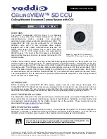
PROCESSOR
VF
FLASH
LENS1
REMOTE
MONITOR
Location and Function of Parts
Rear view
1
VF (viewfinder) connector (DIN 8-pin)
Connect the cable from the viewfinder.
2
MONITOR connector (BNC type)
This outputs a composite video signal. Using a
75-ohm coaxial cable (not supplied), connect this to
the composite video input connector (BNC type) of a
video monitor.
3
FLASH connector (X-contact socket)
Connect the cable from a flash unit.
This connector is not used when the cable from the
flash unit is connected to the FLASH connector on the
digital processor.
4
REMOTE connector (12-pin, female)
Connect the supplied remote controller.
5
LENS1 connector (20-pin, female)
When using the special-purpose lens (VCL-1205BYS),
connect the cable from the lens.
6
PROCESSOR connector (26-pin, male)
Connect this to the CAMERA connector of the digital
processor with the supplied camera cable.
1
VF connector
2
MONITOR connector
3
FLASH connector
4
REMOTE connector
5
LENS1 connector
6
PROCESSOR connector
Содержание DKC-ST5
Страница 6: ......
Страница 20: ......
Страница 44: ......
Страница 62: ......
Страница 68: ...Sony Corporation Printed in Japan ...