5-14
DVS-7000AE IM
5-2. Adjustment of Secondary Power Supply Voltage
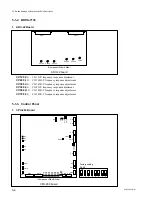
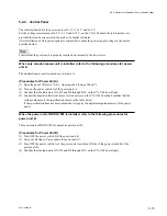
(5) Connect the digital voltmeter between test terminals on the CPU-264 and the XPT-16 boards and
confirm that the voltage value of each test connector meet the specification shown in the table below.
If the specification does not meet, adjust the voltage by the adjustment potentiometers of the power
unit B.
(6) Turn on the power switches of the power units A and B.
(7) Confirm that the indicators of the power units A and B light. If an indicator of both does not light, re-
carry out from the step (1) of “procedures for power unit B”.
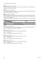
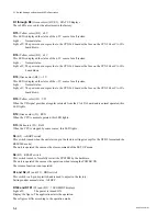
Power unit
Voltage
Specifications
Test connector
Adjustment potentiometer
A
+
5 V (A)
+
5.05
±
0.02 V
CPU-264 board
RE-110 board
CNT3 (
+
5 V)
→→
CNT7 (GND)
1
RV201 (Power unit A)
+
5 V (B)
+
5.05
±
0.02 V
XPT-16 board
RE-110 board
CNT1 (
+
5 V)
→→
CNT3 (GND)
1
RV202 (Power unit A)
+
3 V
+
3.35
±
0.02 V
CPU-264 board
RE-110 board
CNT4 (
+
3 V)
→→
CNT7 (GND)
1
RV203 (Power unit A)
_
5 V
_
5.05
+
0.00 V (
*
1)
CPU-264 board
RE-110 board
_
0.02 V
CNT6 (
_
5 V)
→→
CNT7 (GND)
1
RV204 (Power unit A)
B
+
5 V (A)
+
5.05
±
0.02 V
CPU-264 board
RE-110 board
CNT3 (
+
5 V)
→→
CNT7 (GND)
1
RV201 (Power unit B)
+
5 V (B)
+
5.05
±
0.02 V
XPT-16 board
RE-110 board
CNT1 (
+
5 V)
→→
CNT3 (GND)
1
RV202 (Power unit B)
+
3 V
+
3.35
±
0.02 V
CPU-264 board
RE-110 board
CNT4 (
+
3 V)
→→
CNT7 (GND)
1
RV203 (Power unit B)
_
5 V
_
5.03
+
0.02 V (
*
2)
CPU-264 board
RE-110 board
_
0.00 V
CNT6 (
_
5 V)
→→
CNT7 (GND)
1
RV204 (Power unit B)
(
*
1) For the power unit A the center value of the
_
5 V is
_
5.05 V.
(
*
2) For the power unit B the center value of the
_
5 V is
_
5.03 V.
PWH4
x
8
RV201
+
5 V (A) RV202
+
5 V (B)
RV203
+
3 V
RV204
_
5 V
CNT1
CNT2
CNT3
5V
3V
_
5V
CNT3
CNT4
CNT6
5V
3V
_
5V
CNT7
GND
D15 (B5)
D16 (B5)
D18 (B5)
RE-110 board
Power supply unit
Adjustment driver
XPT-16 board
CPU-264 board


