5-12
DVS-7000AE IM
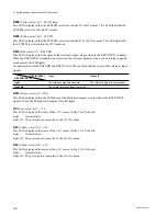
RV2
D9
RV1
RV3
CN5
CN6
CN4
RE-112 board
(Component Side/A Side)
5-1. Switch Settings on Boards and LEDs Description
5-1-4. BKDS-7090
1. RE-112 Board
D9
(Green color) (C4) :
When the power is normal operated, this LED lights.
When the following troubles come up, this LED light off.
In the cases that one power unit is used.
1.
When the power switch in the panel is turned off.
2.
When the fun stops in the power unit.
3.
When the CP1 or CP2 in the power unit is not normal operated.
In the cases that two power units are used.
1.
When the one power switch in the panel is turned off.
2.
When the one fun stops in the power unit.
3.
When the CP1, CP2, CP3 or CP4 in the power unit is not normal operated.
4.
When the voltage of the two power is correctly adjusted.
(The diode on the power unit that is low-level lights off.)
In the steps 1 through 3, the diode on the power unit that is not normal operated lights off.
RV1
(C5) :
+
5 V voltage adjustment
RV2
(C4) :
+
12 V voltage adjustment
RV3
(C5) :
+
3 V voltage adjustment


