4-24
DVS-7000AE IM
4-4. Installation of Options for Control Panel
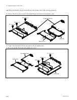
(5) Connect two harnesses (CTRL5 and DC9) as shown in the figure below. Also, when using the
adapter box (BKDS-7075), connect the harness (CTRL10) which is supplied with adapter box
(BKDS-7075) as shown in the figure below.
(6) Turn on the power switches in the control panel.
(Refer to “4-4-2. Turning On/Off the Power Switch”.)
(7) Close the panel. (Refer to “4-4-1. Opening and Closing of Panel”.)
CPU-263 board
KY-322 board
CN4
Harness (DC9)
Harness (CTRL5)
CN4
CN2
CN1
CN3
Harness (CTRL5)
CN2
CN1
CN3
CN3
CN2
Harness (CTRL10)
CN-1143 board
Harness (DC9)
CN4
Harness (DC9)
CN18
KY-324 board

