4-2
DVS-7000AE IM
4-1. Installation of Plug-in Boards
4-1. Installation of Plug-in Boards
DVS-7000A can be used for various systems, and its functions can be extended by selecting the optional
boards. Each plug-in board must be installed in the corresponding slot of DVS-7000A. Confirm that all
the boards are in the specified slots by referring to the following table.
For the details of how to install the plug-in board, refer to “4-3-2. Inserting/Pulling Out of Plug-in
Boards”.
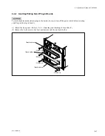
The board name are displayed near the eject lever at the left side on the A side of each plug-in board. The
slot numbers that can be installed the board are displayed on the inside of the front panel of DVS-7000A.
Like the standard board, each optional boards should also be installed in the specified slot according to
the slot number display.
n
(1) Confirm that the connectors on each board are securely connected to the MB-618 board of the main
unit.
(2) If the board is installed in an incorrect slot, a system error occurs. Then the system is not properly
activated.
(3) Be sure to confirm the power supply voltage when an optional board is added or a board is replaced.
(Refer to “5-2. Adjustment of Secondary Power Supply Voltage”.)
1
CPU-264
2
YC-59
MY-66
CC-81
3
4
ENC-34
ADC-22
5
ENC-34
ADC-22
6
CRK-10
CRK-11
7
MIX-35
BD-26
BD-35
8
CRK-10
CRK-11
9
MIX-35
BD-26
BD-35
10
CRK-10
CRK-11
11
MIX-35
BD-26
BD-35
12
OUT-9
13
OUT-9
14
XPT-16
15
XPT-16
16
ADC-21
DI-36
17
ADC-21
DI-36
18
ADC-21
DI-36
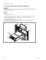
Eject lever
Board name
(A side)
CPU-264


