1-2
DVS-7000AE IM
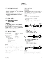
1-3. Connectors
1-3. Connectors
When connecting cables to various connectors on the rear
panel at the time of installing, connecting or servicing,
connect the following connectors or their equivalents.
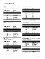
1. DVS-7000A
Connector function name
Connector parts No. and
on rear panel
name of cable
PANEL 1
D-sub 9-pin, Male
DME 1 to 4
Connector 9-pin, Male
SERIAL TALLY
1-560-651-00
(
*
1)
DSK
Junction Shell 9-pin
TERMINAL
1-561-749-00
EDITOR A/REMOTE 1
EDITOR A/REMOTE 2
PANEL 2/REMOTE 3
GPI
D-sub 25-pin, Male
Connector 25-pin, Male
1-560-904-11
(
*
1)
Junction Shell 25-pin
1-563-377-11
PRIMARY INPUTS 1 to 36
BNC Coaxial Connector Plug
DIRECT INPUT
CRK INPUTS 1 to 4
REF INPUT
REF OUTPUT
AUX BUS OUTPUTS 1 to 13
ME-1 to 3 OUTPUTS
PGM OUTPUTS 1 to 4
CLEAN OUTPUT
PST OUTPUT
EDIT PVW OUTPUT
MATRIX
(
*
3)
AC IN
Main Power Supply Cable
(For the details of the cable,
refer to Section 1-2-3.)
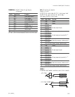
2. BKDS Control Panel
(BKDS-70xx/70xxR/70xxLR)
Connector function name
Connector parts No. and
on rear panel
name of cable
SWITCHER
D-sub 9-pin, Male
DSK
Connector 9-pin,Male
DME
1-560-651-00
(
*
1)
TERMINAL 1 to 2
Junction Shell 9-pin
REMOTE 1 to 5
1-561-749-00
GPI
D-sub 25-pin, Male
Connector 25-pin, Male
1-560-904-11
(
*
1)
Junction Shell 25-pin
1-563-377-11
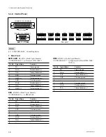
AUX PANEL
BVS Cable
(
*
2)
DISPLAY PANEL
1-574-993-11
OPTION PANEL
AC IN
Main Power Supply Cable
(For the details of the cable,
refer to Section 1-2-3.)
(
*
1) : The following solderless contact must be used for the plug.
AWG #18 to #22:1-566-493-00
AWG #22 to #24:1-564-774-00
AWG #24 to #30:1-564-775-00
(
*
2) : The BVS cables are supplied with the models in the list below.
(
*
3) : Use the 9-pin BNC conversion cable supplied with DVS-7000A.
Model name
DISPLAY
AUX BUS OPTION
TOTAL
PANEL
PANEL
PANEL
BKDS- 701x
1
1
BKDS- 701xR/
1
1
2
701xLR
BKDS- 702x
1
1
2
BKDS- 702xR/
702xLR
1
1
1
3

