Solartron Metrology SI7500 Скачать руководство пользователя страница 24

5.0 Setting up the SI7500 (cont.)

502858  issue 1.1

5.0 Setting up the SI7500 (cont.)

22

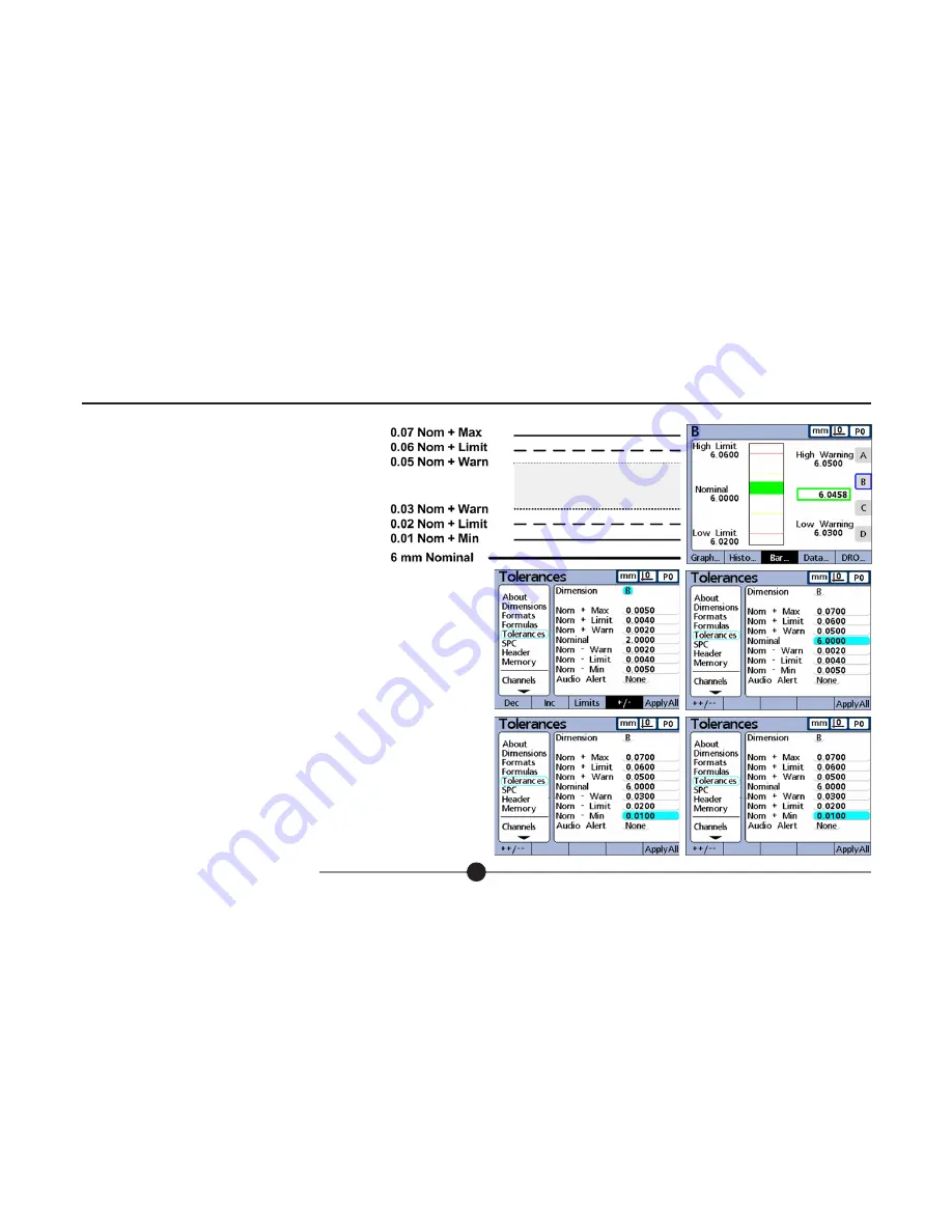
5.8.2 Nominal With ++ Tolerances

A nominal value is displayed with tolerances entirely on 

the plus side of nominal. 

To specify a range of tolerances above the nom inal value 

(+ Tolerance): 

1. Press the +/- softkey

2. Enter the high end of the positive tolerance range into the + Max, + Limit and 

+ Warn fields, and then enter the nomi nal value. 

3. Enter the low end of the positive tolerance range into the -Warn, and press 

the ++/--  softkey to change the fields to + Warn. 

Repeat this proce dure for the - Limit and - Min fields. This establishes the lower 

end of the positive range of tolerances. 

Содержание SI7500

Страница 1: ...SI7500 ORBIT Digital Display Quick start guide...

Страница 2: ...f this document may be reproduced or transmitted in any form or by means electronic or mechanical for any purpose without the express permission of Solartron Metrology 2008 Solartron Metrology Ltd All...

Страница 3: ...uct A Measurement 36 6 5 Review Measurement Data 36 6 6 Send Or Report Results 37 Section Contents Page 1 0 About this Manual 2 2 0 Safety Information 3 3 0 Introduction to the SI7500 5 3 1 Functional...

Страница 4: ...installation guide it is intended as an aid for new users to familiarise themselves with the SI7500 digital readout and it s functionality For more detailed information on the SI7500 and it s function...

Страница 5: ...s Safety considerations are related to power connections and physical mounting WARNING If the SI7500 falls from its mounting location serious personal injury or damage to the equipment can result Powe...

Страница 6: ...tripping hazards with power cords input cables and other electrical wiring Use shielded cables to connect to the parallel serial RS 232 and RS 485 ports Make certain that cables are properly terminat...

Страница 7: ...ders and other sensors as part of in line production activities or final quality inspection Measurements can be conducted completely under operator control or can be semi automated and conducted in co...

Страница 8: ...tical bar Dial Digital readout DRO Graph of values Histogram of values Measurement data SPC data The SI7500 s user interface screens include a digital readout of current values bar and dial position v...

Страница 9: ...keys Numeric keypad Cursor keys Command keys Softkeys Softkeys are used to select options displayed at the bottom of the LCD screen Particular options are selected by press ing the softkey immediately...

Страница 10: ...cursor keys move the cursor around the screen and allow the user to cycle through the available options The keypad is used for the entry of numerical data The command keys are used to confirm option...

Страница 11: ...n using the SI7500 The next few sections in this guide will address each step in turn Connect Orbit hardware Assign Orbit modules to channel inputs Create a part dimensions Assign formulas to dimensio...

Страница 12: ...ement for an extra power supply or Orbit Interface module The Orbit network must be connected to the SI7500 with the 9 way cable supplied to ensure proper function of the measuring system If a longer...

Страница 13: ...11 Plug cable into RS 485 port at rear of unit see above The Orbit network and SI7500 should be connected in the way illustrated solartron 6 9 5 1 solartron Screened 9 way serial cable Installation us...

Страница 14: ...een After connecting the SI7500 to Orbit modules as above apply power to the unit Once the DRO screen is displayed navigate to the setup menu by pressing the relevant softkeys for Menu Setup The About...

Страница 15: ...or password must be entered in order to modify setup menu options From the About screen of the setup menu navigate to the Supervisor screen using the cursor keys Press the right arrow cursor to select...

Страница 16: ...the Channel screen from the setup menu Select the channel number of choice using the decrement increment softkeys Move the cursor to the Id field Select either a Teach or b Entry with the relevant sof...

Страница 17: ...he PIE case connected to the T CON To enter the Id code select the desired characters with the cursor keys and use the Enter and Cancel keys to respectively enter or delete a character Numerals are wr...

Страница 18: ...t including probe setup tolerances data handling details etc Each Part can contain up to 16 Dimensions these are the features the fixture measures and are what will be displayed by SI7500 as measureme...

Страница 19: ...s and not displayed Hidden dimensions are not printed on re ports or sent to computers as data files Visible and hidden dimensions use the same naming con vention Pressing the Visible or Hidden softke...

Страница 20: ...surement process and many other functions This section of the guide will demonstrate how to setup a Formula for more detailed information and a list of Formulas available on the SI7500 please refer to...

Страница 21: ...o construct formulas Once displayed formula functions are selected using the dimension keys at the right of the screen Repeatedly pressing any bottom softkey displays multiple sets of related function...

Страница 22: ...rrent Value bar and dial screens The default bar and dial displays show Pass val ues in green Warning values in yellow and Fail values in red Cycle through the Setup menu to the Tolerances screen Pres...

Страница 23: ...lerances and then highlight the desired fields and then use the numeric keypad to enter values This example screen to the right contains the nominal value and tolerances listed below Nominal 2 0000 mm...

Страница 24: ...rances above the nom inal value Tolerance 1 Press the softkey 2 Enter the high end of the positive tolerance range into the Max Limit and Warn fields and then enter the nomi nal value 3 Enter the low...

Страница 25: ...s below the nom inal value Tolerance 1 Press the softkey 2 Enter the low end of the negative tolerance range into the Max Limit and Warn fields and then enter the Nomi nal value 3 Enter the high end o...

Страница 26: ...bove and below a nomi nal value 1 Press the Limits softkey to specify a nomi nal value with fixed limits 2 Highlight the desired fields and then use the numeric keypad to enter val ues The example bel...

Страница 27: ...ID numbers can also be viewed or changed Use the numeric keypad to specify the desired number of samples to be included in each sub group Each subgroup can contain from 1 to 10 samples SPC parameters...

Страница 28: ...ed on graphs and can be included in printed reports and trans mitted data Normally the Next Record ID field starts at 1 and is automatically incremented by the system each time a new record is stored...

Страница 29: ...The limits are used by the SI7500 graphing soft ware to scale the value axis of SPC graphs CAUTION The UCL and LCL values shown on the SPC setup screen should not be altered after initial setup Change...

Страница 30: ...ted by highlighting either of the Xbar control limit fields and pressing the Recalc softkey Alternatively the x upper and lower control lim its can be entered directly into the Xbar Ucl and Xbar Lcl f...

Страница 31: ...he Recalc softkey Alternatively the r upper and lower control lim its can be entered directly into the Ucl and Lcl fields using the numeric keypad The Warning Per field is used to speci fy the upper a...

Страница 32: ...ing the RS 232 serial port settings for communication with a computer or RS 232 channel input device Where possible the settings should be identical to those on the receiving device UART ID For commun...

Страница 33: ...racter is transmitted This de lay can be increased or decreased to accom modate various serial devices Use the numeric keypad to specify delays in milliseconds from 0 to 10 seconds between characters...

Страница 34: ...SB flash drive Files stored on flash drives are named DataN txt by the SI7500 system where N denotes the number of the data file File type The USB port data file type can be specified to replace exist...

Страница 35: ...h memory stick The settings can later be copied onto the same or another SI7500 to refresh a configuration or to speed the installation procedure in applications using several units 1 With a USB flash...

Страница 36: ...rt below details a standard SI7500 measurement process 6 2 Selecting A Part To select a part 1 Press the Menu softkey the Extra softkey and use the cursor keys to highlight Cycle or Part 2 Press Enter...

Страница 37: ...tructions for this procedure can be found in chapter 5 of the SI7500 User Manual document number 502823 To calibrate a single reference point from the main display screen DRO screen is default 1 Press...

Страница 38: ...red and saved into the instrument s internal memory Data capture can be triggered by RS 232 external I O input footswitch or most simply by manually pressing the Enter key 6 5 Review Measurement Data...

Страница 39: ...lists all the data output formats the SI7500 can provide and from what display screen to generate them Report type Screen User actions Current dimensions Numeric display DRO Press Print key Graphs of...

Отзывы: