


38
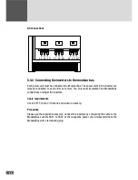
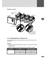
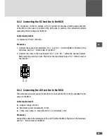
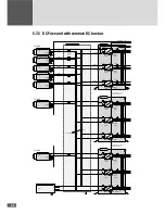
5.4.4 Connecting the MCU to the modular bus
Cable requirements
Cat. 6 S/FTP cable, 5 metres (included in delivery)
Procedure
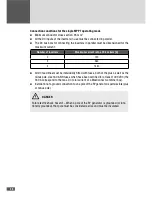
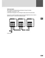
1. Connect the cable to the modular bus “X802” socket of the MCU.
2. Connect the cable to a free modular bus socket (X631 or X632) at the nearest power
unit, see also 5.3.4 “Connecting inverters to the modular bus”.
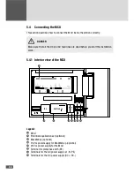
5.4.5 Connecting the protective earth (PE) line to the MCU
Cable requirements
■
■
Minimum cable cross section: 6 mm
2
, maximum cable cross section: 16 mm
2
■
■
The MCU must be grounded independently of the inverters.
Procedure
Connect the protective earth to the 16 mm
2
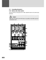
terminal. The position of the terminal: see
5.4.1 “Interior view of the MCU”.
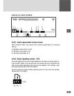
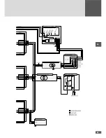
5.4.6 Interface and contacts of the MCU
Integrated RS485 and Ethernet interfaces enable many communications and monitoring
options based on our MaxComm communications platform. The system communicates
either directly via a PC with MaxTalk (from version 2.0) or via the Internet enabled
MaxWeb xp data logger.
In addition, contacts for switching the inverters on and off, for remote monitoring of the
MCU, for a MaxConnect alarm input as well as contacts for connecting the potential
equalization set (PAS) are integrated.
NOTE
Additional information on the use of various interfaces and functions of the MCU can
be found in the operating manual of the TS-SV inverter.
Содержание TS-SV
Страница 1: ...Installation manual SolarMax TS SV 330TS SV 360TS SV...
Страница 3: ......
Страница 45: ...45 en...
Страница 47: ...47 en...


