background image

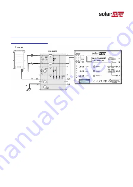
For further information, see the 

Overvoltage Surge Protection 

Technical Note: 

https://www.solaredge.com/sites/default/files/lightning_

surge_protection.pdf

Figure 23: Protection connection 

Energy Meter with Modbus Connection Installation Guide MAN-01-00269-1.5

74

   Appendix E: External Lightning Protection

Содержание SE-WND-3Y400-MB-K2

Страница 1: ...Installation Guide Energy Meter with Modbus Connection Version 1 5...

Страница 2: ...he right to make changes to the material at any time and without notice You may refer to the SolarEdge web site www solaredge com for the most updated version All company and brand products and servic...

Страница 3: ...radio communications However there is no guarantee that interference will not occur in a particular installation If this equipment does cause harmful interference to radio or television reception whic...

Страница 4: ...n and Repeater are installed near other 2 4 GHz emitting devices such as dual technology PIR detectors used in alarm systems microwave ovens etc This might degrade disable the gateway repeater operati...

Страница 5: ...e Version 1 2 July 2018 Firmware version support update Version 1 1 May 2018 Product name update Model SE WND 3Y400 MB K2 Accuracy 1 of Rated CT Current Supports UK Engineering Recommendation G100 Iss...

Страница 6: ...on Guidelines 15 Installing and Connecting the Meter 17 Chapter 3 Configuration 26 SolarEdge Device Firmware Version 26 Device Configuration 29 Appendix A Troubleshooting Meter Connection 43 Troublesh...

Страница 7: ...endix C Monitoring Platform Meter Data 64 Appendix D Meter Technical Specifications 68 Appendix E External Lightning Protection 73 Support Contact Information 75 Energy Meter with Modbus Connection In...

Страница 8: ...WARNING Denotes a hazard It calls attention to a procedure that if not correctly performed or adhered to could result in injury or loss of life Do not proceed beyond a warning note until the indicate...

Страница 9: ...tion about safety issues Disposal requirements under the Waste Electrical and Electronic Equipment WEEE regulations NOTE Discard this product according to local regulations or send it back to SolarEdg...

Страница 10: ...r consumed by the site Consumption meter A meter that is installed at the load consumption point and measures the energy power consumed by the site Self consumption The PV power consumed by the site a...

Страница 11: ...nnected at a single neutral point Wye systems utilize five wires three hot one neutral and one ground Delta In a Delta configuration the three phases are connected in a triangle Delta systems utilize...

Страница 12: ...ns Production metering Consumption monitoring Export limitation Smart Energy on grid applications The SolarEdge inverter or the Commercial Gateway reads the exported imported power from a meter instal...

Страница 13: ...Figure 4 Typical installation with consumption meter Meter Connection Options In a single inverter system the meter is connected directly to the inverter Energy Meter with Modbus Connection Installat...

Страница 14: ...RS485 port use this port to connect between the inverters If the inverter has only one RS485 port use an RS485 Plug In available from SolarEdge or ZigBee communication between the inverters 1 This fig...

Страница 15: ...econd RS485 port can be used to create an RS485 bus for communication between the inverters This option is illustrated in Figure 6 Figure 6 Multi inverter connection with Commercial Gateway and meter...

Страница 16: ...n 3 wire shielded twisted pair a 4 wire cable may be used Wire cross section area 0 2 1 mm 24 18 AWG a CAT5 cable may be used NOTE If using a cable longer than 10 m 33 ft in areas where there is a ris...

Страница 17: ...ar the meter and be easily operated Use circuit breakers or fuses rated for 20A or less Use grouped circuit breakers when monitoring more than one line The circuit breakers or fuses must protect the m...

Страница 18: ...two mounting holes on both sides of the meter to mark the hole positions NOTE Do not use the meter as a drilling guide the drill may damage the screw terminals and metal shavings may fall into the con...

Страница 19: ...both sides of the meter 2 Attach the DIN rail clips to the meter and fasten them using the supplied screws torque 0 7 N m 0 5 lb ft Make sure that the clips are correctly oriented as shown below Figur...

Страница 20: ...ansformers 2 Install the CTs around the conductor to be measured Split core CTs can be opened for installation around a conductor A nylon cable tie may be secured around the CT to prevent accidental o...

Страница 21: ...efer to Installing Two Meters on page 52 Figure 9 Meter connections NOTE Clamp the CT connected to L1 CT around the wire connected to L1 Clamp the CT connected to L2 CT around the wire connected to L2...

Страница 22: ...and cannot be pulled out easily e Insert the 10 pin terminal block into the socket on the meter making sure it is fully seated in the meter 3 Connect the CT wires to the 6 pin terminal block a Connec...

Страница 23: ...nd 6 to 0 DOWN b Switch 7 Set to 1 UP if 120 ohm termination is required Otherwise set to 0 DOWN c Switch 8 Set to 0 DOWN To connect the meter to the inverter or Commercial Gateway 1 If connecting to...

Страница 24: ...ngle and Three Phase Inverter Inverter with HD Wave technology Figure 11 Inverter RS485 connectors Inverter RS485 Plug in pull out the 3 pin connector Figure 12 RS485 Plug in on Single Three Phase inv...

Страница 25: ...ith the Commercial Gateway Connect it to the RS485 2 connection on the Commercial Gateway Figure 14 Commercial Gateway RS485 connector 3 Connect the wires as shown below Figure 15 Meter RS485 connecti...

Страница 26: ...witch inside the inverter to ON top position The switch is located on the communication board and is marked SW7 Commercial Gateway Terminate by switching the SW2 termination DIP switch to ON Figure 16...

Страница 27: ...ion board firmware CPU version is 4 2 xxx or later To check the inverter CPU version 1 Verify that the inverter has been activated using the activation card supplied with the inverter 2 To check the C...

Страница 28: ...Log Warning Log Devices with a display Short press the LCD light button on the inverter until the screen below is displayed C P U 0 0 0 3 1 9 x x C o u n t r y E S P 3 To upgrade inverters with earlie...

Страница 29: ...Energy Meter with Modbus Connection Installation Guide MAN 01 00269 1 5 28 SolarEdge Device Firmware Version...

Страница 30: ...ations https www solaredge com sites default files storedge_ interface_installation_guide pdf NOTE Calculated meter readings such as self consumption are calculated using the data measured by the mete...

Страница 31: ...tocol Modbus Multi Device 3 Return to the RS485 x Menu and select Add Modbus Device Meter A meter identified as Meter n where n 1 2 3 is created The RS485 x Menu reappears 4 Select Meter n where n is...

Страница 32: ...Figure 17 Meter Configuration Energy Meter with Modbus Connection Installation Guide MAN 01 00269 1 5 Chapter 3 Configuration 31...

Страница 33: ...eter is installed at the inverter output and reads the energy produced by inverters at the site Ext Production The meter is used for export limitation with 3rd party generators and for AC coupling wit...

Страница 34: ...ase loss is set automatically to Enabled Figure 18 CT Phase Loss Menu 9 Select CT Rating and enter the current transformer s rating in amperes Energy Meter with Modbus Connection Installation Guide MA...

Страница 35: ...of the currently entered parameter or to the previous menu Up 1 and Down 2 Moves the cursor to the relevant menu option Enter 3 Used to select an option 1 Verify that the device ON OFF switch is OFF...

Страница 36: ...screen similar to the following is displayed the example here appears in master slave installations D e v i c e T y p e S E P r o t o c o l M D e v i c e I D 1 S l a v e D e t e c t L o n g S L V D e...

Страница 37: ...i n g 0 M e t e r F u n c N o n e T o p o l o g y W y e P T S c a l i n g 1 9 Configure the meter parameters as follows Select Protocol WN Select Device ID 2 Set CT Phase Loss to En enabled In the sub...

Страница 38: ...ocation E x p o r t I m p o r t E x p o r t C o n s u m p t i o n P r o d u c t i o n E x t P r o d u c t i o n I m p o r t N o n e Export Import The meter is installed at the grid connection point an...

Страница 39: ...nverters Import The meter is installed at the grid connection point and reads the import energy None No reading The selected option is displayed in the RS485 Conf screen as E I E Cons Prod I None Sele...

Страница 40: ...more meters is connected to the RS485 1 or RS485 2 bus Communication LAN Connected RS485 1 Modbus 2 of 2 RS485 2 SE Slave None Cellular N A Wi Fi NC ZigBee NC 3 Continue scrolling to the Meters sectio...

Страница 41: ...internal meter error occurs it will be displayed here Refer to Power The exported or imported power Energy The total energy read by the meter Meters Production Meter SN XXXXXXXX RS485 2 Modbus ID 1 S...

Страница 42: ...red 2 Verify that the setting of the relevant RS485 port is correct and that the port is communicating with the meter For example if the meter is connected to the RS485 1 port the Communication status...

Страница 43: ...e r W x x x x x x E n e r g y W h x x x x x x Status Displays the state of communications between the meter and the inverter Displays OK if the meter is communicating with the inverter Error message...

Страница 44: ...Two Meters on page 52 Troubleshooting the Meter using SetApp Communications Failure The following are indications of a connectivity failure between the inverter and the meter If NC not connected appe...

Страница 45: ...eft hand corner of the Inverters section of the Status page Error 3x6E Meter Comm Error If the status in the Meters section of the Status page is Comm Error Meters Export Meter RS485 1 Modbus ID 2 Sta...

Страница 46: ...red in the chapter Configuration on page 26 Check for water damage or sealing problems Inspect the entire conduit run for possible points of water penetration and fix leaks Ensure that proper outdoor...

Страница 47: ...is consuming power check the following There are no loose connections at the inverter connectors and at the meter specifically the AC wiring on the meter s AC wiring connector The CT black and white c...

Страница 48: ...munication status screen should display the following D e v P r o t R S 4 8 5 1 M T R S E 1 R S 4 8 5 2 Z i g B e e Device Type or Protocol are configured incorrectly If MTR meter is not displayed as...

Страница 49: ...cating with the inverter Check the following Check the meter s DIP switch settings The switches should be set as follows Check that switches 1 6 correctly specify the meter address To set the address...

Страница 50: ...oubleshooting E x p o r t M e t e r S t a t u s O K E r r o r P o w e r W x x x x x x E n e r g y W h x x x x x x OK is not displayed If OK is not displayed in the Status line of the status screen sho...

Страница 51: ...teady value although the the site is consuming power check the following There are no loose connections at the inverter connectors and at the meter specifically the AC wiring on the meter 10 pin conne...

Страница 52: ...m NOTE The above meter setup is for single phase applications The meter supports three phase applications as well Energy Meter with Modbus Connection Installation Guide MAN 01 00269 1 5 Appendix A Tro...

Страница 53: ...tightening RS485 wiring is daisy chained between meters as described in the following figure Figure 20 RS485 chain of meters Connecting Two Meters 1 Connect the twisted pair wiring to the meters as sh...

Страница 54: ...6 to 0 DOWN b Switch 7 Set to 1 UP if 120 ohm termination is required Otherwise set to 0 DOWN c Switch 8 Set to 0 DOWN 4 Set the other meter s DIP switches to address 1 a Set switch 1 to 1 UP and swit...

Страница 55: ...0 DOWN c Switch 8 Set to 0 DOWN 5 Terminate the SolarEdge device as described in Installing and Connecting the Meter on page 17 Energy Meter with Modbus Connection Installation Guide MAN 01 00269 1 5...

Страница 56: ...Connection Using SetApp In the sample configuration described below a production meter is set to address 1 and an export import meter is set to address 2 The meters use the WattNode protocol To config...

Страница 57: ...output and reads the energy produced by the inverters at the site Ext Production The meter is used for export limitation with 3rd party generators and for AC coupling with non SolarEdge inverters 5 Se...

Страница 58: ...Conf The following screen is displayed D e v i c e T y p e S E P r o t o c o l M D e v i c e I D 1 S l a v e D e t e c t L o n g S L V D e t e c t S l a v e L i s t M u l t i I n v S e t 2 Select Dev...

Страница 59: ...le of a Consumption meter set to address 1 and an Export Import meter set to address 2 Select Meter 1 The following is displayed D e v i c e T y p e M T R P r o t o c o l W N D e v i c e I D 2 C T R a...

Страница 60: ...duction Set Topology to Wye Select Meter 2 and configure its settings Select Device Type Revenue Meter Select Protocol WattNode Set Device ID 2 Set the CT Rating to the value that appears on the CT If...

Страница 61: ...external button until the Communication status screen is displayed as shown below When two meters are connected a screen similar to the following should appear w w w w w w w D e v P r o t R S 4 8 5 1...

Страница 62: ...t meter E x p o r t M e t e r S t a t u s O K E r r o r M e s s a g e T o t a l W h X X X X X X X Status Displays OK if the meter is communicating with the communication board Error message If an inte...

Страница 63: ...ear in the Communication status screen w w w w w w w D e v P r o t R S 4 8 5 1 M L T 0 2 0 2 R S 4 8 5 2 Z i g B e e Device Type or Protocol are configured incorrectly If MLT multiple meters is not di...

Страница 64: ...on status screen shown above at least one of the meters is not communicating with the inverter Check the following Check the RS485 Modbus address DIP switch settings as specified in Connecting Two Met...

Страница 65: ...o as virtual meters such as self consumption are calculated using the data measured by the meter and the inverters The data from the inverters and from installed meters is displayed in the Dashboard a...

Страница 66: ...Dashboard Displayed in Monitoring Charts Production inverter site a a Consumption X X Self consumption X X Export X X Import X X Energy Meter with Modbus Connection Installation Guide MAN 01 00269 1...

Страница 67: ...nsumption a calculated a calculated a calculated a calculated Export X a X a Import X a X X 1 S0 meters are supported only by inverters with a display 2 When installing an S0 meter at the grid connect...

Страница 68: ...Charts Production inverter site a a a a Consumption a a a a Self consumption a calculated a calculated a calculated a calculated Export X a calculated X a calculated Import X a calculated X X 1 S0 me...

Страница 69: ...Three Phase L1 L 2 L3 N PE Power Consumption typ 1 8 W COMMUNICATION Supported Communication Interfaces Modbus RS485 Response time 1 2 sec Default Device ID Modbus 2 1 PE Protective Earth connection i...

Страница 70: ...1 100 of Rated CT Current 1 0 Hi Accuracy Revenue Generation ANSI C12 20 Class 5 1 Using ACT 0750 CT models Energy Meter with Modbus Connection Installation Guide MAN 01 00269 1 5 Appendix D Meter Tec...

Страница 71: ...ons HxWxD 85 x 153 38 mm Weight 310 gm Enclosure type High impact ABS and or ABS PC plastic UL 94V 0 IEC FV 0 Operating Temperature Range 30 to 55 C Relative Humidity noncondensing 5 90 Protection Rat...

Страница 72: ...CT 0750 50 50 20 x 20 61 x 60 4 SE ACT 0750 100 100 SE ACT 0750 250 250 SE CTS 2000 1000 1000 50 8 x 50 8 121 x 127 Mechanical specifications 1 One current transformer per phase for other ratings cont...

Страница 73: ...Energy Meter with Modbus Connection Installation Guide MAN 01 00269 1 5 72 Appendix D Meter Technical Specifications...

Страница 74: ...earth ground of the SolarEdge device This ground connection is crucial for proper suppression device operation The ground connection should be made using a heavy gauge wire and kept as short as possib...

Страница 75: ...Protection Technical Note https www solaredge com sites default files lightning_ surge_protection pdf Figure 23 Protection connection Energy Meter with Modbus Connection Installation Guide MAN 01 0026...

Страница 76: ...e product SetApp mobile application LCD screen or on the monitoring platform or by the LEDs if there is such an indication System configuration information including the type and number of modules con...

Страница 77: ......

Отзывы: