UPS for 400 Vac Grid, Installation Guide, doc. rel. 3.0
65
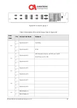
Figure 48: Connector group 2
Table 8: Description of Connector Group 2 (Key to Figure 48)
P
LUG
NAME
P
IN
C
ONNECTION
N
AME
C
OMMENT
P1
1
Digital output #1
Low Battery
2
3
Digital output #2
AC fail
4
P2
1
Digital output #3
LVD (this works in tandem with P13 pins 1 and 3)
Do NOT remove P2 or P13
2
3
Digital output #4
4
P3
1
Digital output #5
2
3
Digital output #6
4
P4
1
Digital output #7
2
3
Digital output #8
4
P5
1
RS485 Modbus A
2
RS485 Modbus B
Содержание Gamatronic B300
Страница 91: ...UPS for 400 Vac Grid Installation Guide doc rel 3 0 83 Figure 60 Connection diagram for 2 parallel units ...
Страница 92: ...84 UPS for 400 Vac Grid Installation Guide doc rel 3 0 Figure 61 Connection diagram for 4 Units in Parallel ...
Страница 95: ...UPS for 400 Vac Grid Installation Guide doc rel 3 0 87 7 1 Circuit Breaker Layout Figure 62 Electrical setup ...


