June 2020
|
Solar Stik
®
, Inc.
38
|
24VDC PRO-Verter 5000-120 AGS Operator Manual
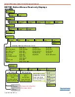
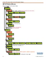
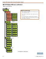
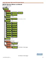
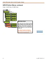
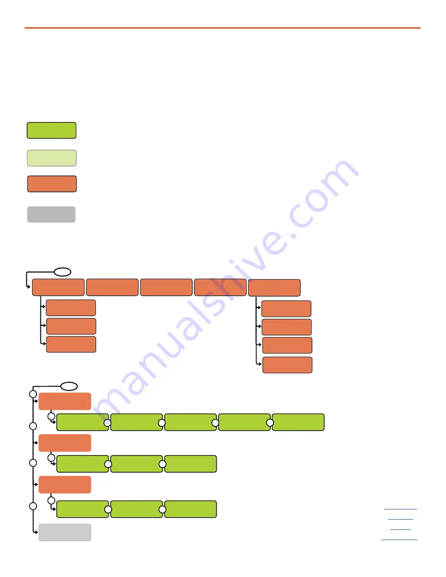
Programming Menu Map
CTRL
01 AC In Control
Auto Connect
02 CHG Control
Multi-Stage
03 Gen Control
AUTO
Set AC In Control
Auto Connect
Set CHG Control
Multi-Stage
Set Gen Control
AUTO
Set AC In Control
VDC Connect
Set CHG Control
Start Float
Set Gen Control
ON
Set AC In Control
Time Connect
Set CHG Control
Start Bulk
Set Gen Control
OFF
Set AC In Control
SOC Connect
Set AC In Control
AC In - Disabled
04 PT Control
Press Select
(See
Setup Button 04 Menu Options)
Feature not utilized by
PRO-Verter 5000
CTRL Button Menus
R
R
R
R
R
R
R
R
P
P
P
R
R
R
R
FAVS Button Menus
FAVS
F1 Battery Type
CC/CV
F4 LBCO
24.4 Volts
F2 AmpHour Size
360AH
F3 AC Input
Amps = 30A
F5 Gen Run VDC
Set Stop Gen
Volts = 28.8
Set Stop Volts
Delay = 1 Min
Set Start Gen
Volts = 25.0
Set Start Volts
Delay = 15 sec
Set CV Chg Done
HOLD CV/CHG VDC
Set CV Charge
Volts =
29.0
Set Max Charge
AMPS =
110
Orange menu items indicate values set by Solar Stik for a specific application. These
values (with the exception of setting the clock to local time) should not be changed by
the user without consulting [email protected].
Green menu items represent factory default settings, read-only settings, or options that
exist within a specific menu item.
Gray menu items highlight features NOT currently used in the PRO-Verter 5000. If
TECH: 07 Show All Menus = “No”, then items in a gray window will not be visible to
the user.
Light green menu items represent resettable menu selections. Press and hold the knob
for 3 seconds to reset values.
Menu Map Color Coding Key
The PRO-Verter has been programmed at the factory to operate with LiFePO
4
batteries. The
programming map on the following pages is a representation of how to navigate the information
in the PRO-Verter user interface. The color coding key below provides information to make
understanding the programming map easier.


