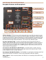
June 2020
|
Solar Stik
®
, Inc.
30
|
24VDC PRO-Verter 5000-120 AGS Operator Manual
LED
Status
Meaning
PWR
(GREEN)
OFF
(1) PRO-Verter is disabled;
(2) User interface is in Power Save mode —press any button to activate LEDs;
(3) No power to user interface (check cable or the power to the inverter); or
(4) No AC power at the inverter’s AC output terminals.
ON
AC power is available from the inverter, utility, or generator at the PRO-Verter AC
output terminals.
Fault
OFF
Normal operation
ON
A fault condition has been detected. Check the LCD screen to find and correct the
cause.
CHG
(GREEN)
OFF
(1) User interface is in Power Save mode—press any button to activate LEDs; or
(2) Charger is off—no utility or AC generator present.
ON
Charger steady on. See the LCD screen to determine charge status.
BLINKING, display
says “Charger
Standby”
The charger is in Charger Standby mode. This occurs when the Charger ON/OFF
button is pressed to disable the charger.
BLINKING,
display shows a
charging status
The charger current is automatically decreased because
(1) Charger Back-off—the inverter’s internal temperature is getting hot, and the
current is decreased to reduce/maintain temperature; or
(2) Low AC Input Voltage—the input AC voltage is low, and the charger is disabled
to help stabilize incoming AC voltage to prevent AC disconnect.
BLINKING,
display does
not show any
charge status
The inverter is detecting and qualifying AC voltage (from utility or an AC generator)
on the inverter’s AC input terminals.
INV
(GREEN)
OFF
(1) Inverter is disabled; or
(2) The User Interface is in Power Save mode—press any button to activate the
LEDs.
ON
Inverter is enabled.
(1) Inverter supplies AC power on the output; or
(2) In Inverter Standby (if both INV and CHG LEDs are on), the inverter will
automatically supply AC power to the loads if utility or generator power is lost.
BLINKING
Inverter is in Search mode. (The AC load is below the SETUP: 02A Search Watts
setting.)
Table 1. LED System Status Indicator Guide
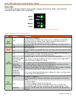
Status LEDs
Four (4) status indicator LEDs for power, faults, charging and Inverting. Table 1 below lists the
meaning for each state of the four (4) LEDs.
Power >
Fault >
Charge >
Invert >
Figure 15. PRO-Verter / System Status LEDs

