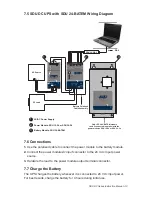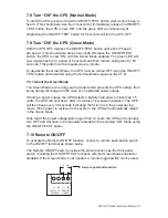
SDU DC Series Instruction Manual • 13
2.
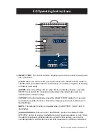
BATTERY FAULT (Red LED):
The red LED illuminates when the UPS is expe-
riencing an overload condition. The LED flashes when the battery is no longer
useful or not connected.
3.
BATTERY MODE/BATTERY CHARGE (Amber LED):
The amber LED illumi-
nates when the UPS is supplying battery power to the loads. The LED flashes
when the battery is charging.
4. INPUT POWER OK (Green LED):
The green LED will illuminate when the dc
input power is normal.
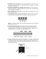
5. Dc Input/Output Screw Terminal Connections:
IP20 rated input and output
screw terminals; acceptable wiring: 16–12 AWG, copper conductor, 90°C.
-
+
-
+
Output DC
Input DC
24V
24V
NOTE:
The maximum length of the connection between the power module and
battery is 6 ft. (1.85 m).
6. Dry Contact Relay Terminals:
The power module incorporates dry relay
contacts for remote signaling of the battery status, terminal connection for
remote ON/OFF, and output dc 24 V/35 mA for powering the auxiliary circuit.
Acceptable wiring: 16–12 AWG, copper conductor, 90°C.
OUTPUT DC
24V/35mA
REMOTE
ON / OFF
NC C NO
BATTERY FAULT
NC C NO
ON BATTERY
NC C NO
LOW BATTERY
13 12 11 10
9
8
7
6
5
4
3
2
1
7. Polarized Terminal Connections for the Battery (+ red color; - black color):
Composed of two PP 15/45 Anderson contacts and two PP 15/45 Anderson
powerpole housings to ensure a keyed connection between the power module
and the battery module.
Bottom View
7


