background image

SDU DC Series Instruction Manual • 11

7.8 Turn “ON” the UPS (Normal Mode)

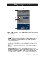
To start the UPS, press and hold the ON/OFF/TEST button until a short “beep” is 
heard. (This should take less than 3 seconds.) Immediately release the ON/OFF/

TEST button; the UPS is now “ON” and the green LED is continuously lit.

Depressing the ON/OFF/TEST button for 5 seconds will turn the UPS OFF.

7.9 Turn “ON” the UPS (Green Mode)

With the UPS OFF, depress the ON/OFF/TEST button until 2 short “beeps” 
are heard. (This should take about 4 seconds.) Release the ON/OFF/TEST 

button; the UPS is now “ON” with the Green Mode enabled. The green 

LED will 

now double flash for a period of 5 seconds and then remain solid green for 55 

seconds. This pattern will be repeated every minute.

To deactivate the Green Mode, the UPS must be turned OFF using the ON/OFF/

TEST button and restarted using the Normal Mode sequence (See 7.8).

7.9.1 About the Green Mode

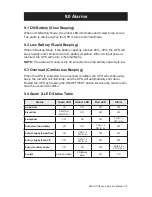
The Green Mode is an energy saving feature that prevents the UPS battery from 
being deeply discharged in the case of an extended power outage.

If during a power outage the UPS detects a battery load power of less than 15 
watts, the UPS will shut down after 3 minutes of low power operation. The UPS 
will then beep every 30 seconds indicating that it is now in the power saving 
mode. When power is restored to the system, the UPS will automatically restart 
in the Green Mode. 

Note that if the power outage lasts longer than 72 hours the UPS will completely 
turn OFF and will have to be manually restarted in the selected “ON” Mode using 
the ON/OFF/TEST button.

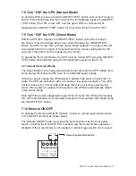
7.10 Remote ON/OFF

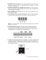
To activate the Remote ON/OFF function, connect a remote push-button switch 
to the ON/OFF terminal as shown below.

The Remote ON/OFF switch provides the same functions as the front panel 
switch, including the ON/OFF/TEST functions with the Green Mode enabled or 
disabled. If the Green Mode is not needed, a remote toggle switch can be used.

OUTPUT DC

24V/35mA

REMOTE

ON/OFF

Remote push-button switch

Содержание SDU 10-24

Страница 1: ...Uninterruptible Power Systems SDU DC Series Instruction Manual...

Страница 2: ...ims all liability for damages resulting from use of this information or for any errors or omissions 2008 SolaHD All rights reserved throughout the world Specifications are subject to change without no...

Страница 3: ...8 0 Operating Instructions 12 13 9 0 Alarms 14 9 1 ON Battery 14 9 2 Low Battery 14 9 3 Overload 14 9 4 Alarm LED Status Table 14 10 0 Replacing the Battery 15 22 10 1 SDU 24 BAT Replacement Batteries...

Страница 4: ...pply To reduce the risk of electric shock do not remove the cover For service contact a qualified technician The UPS contains its own energy source batteries The output terminals may carry live voltag...

Страница 5: ...the UPS The UPS does not operate in accordance with the instruction manual 1 2 Conditions of Use Your UPS provides conditioned power to connected equipment The maximum load must not exceed that shown...

Страница 6: ...ese limits are designed to provide reasonable protection against harmful interference in an industrial installation This equipment uses generates and can radiate radio frequency energy and if not inst...

Страница 7: ...ssis mounting brackets to secure the UPS to the wall back of the panel or enclosure 5 0 Battery Options Two battery modules are available SDU 24 BAT 24 V DIN rail panel mount battery module cable incl...

Страница 8: ...h the unit downward until it stops 4 Push at the lower front edge to lock Gently shake the unit to ensure that the retainer has locked 7 2 1 Removing the Unit from the DIN Rail 1 Push the button and s...

Страница 9: ...BATTERY FAULT BATTERY MODE BATTERY CHARGE INPUT POWER OK Industrial DC UPS SDU 10 24 OUTPUT DC 24V 35mA REMOTE ON OFF NC C NO BATTERY FAULT NC C NO ON BATTERY NC C NO LOW BATTERY 24Vdc 10A 24Vdc 10A I...

Страница 10: ...olarized Cable Assembly O A L S SDU 24 BATEM Industrial DC UPS External Battery Module AC Source 1 2 3 1 AC DC Power Supply 2 Power Module SDU 10 24 or SDU 20 24 3 Battery Module SDU 24 BATEM Only 1 S...

Страница 11: ...e Green Mode The Green Mode is an energy saving feature that prevents the UPS battery from being deeply discharged in the case of an extended power outage If during a power outage the UPS detects a ba...

Страница 12: ...battery cold start 2 OFF When the UPS is ON in either Normal or Battery Mode press the ON OFF Test button for 5 seconds to shut down the output dc power an audible alarm sounds briefly 3 TEST In the N...

Страница 13: ...conductor 90 C Output DC Input DC 24V 24V NOTE The maximum length of the connection between the power module and battery is 6 ft 1 85 m 6 Dry Contact Relay Terminals The power module incorporates dry...

Страница 14: ...hen the UPS is subjected to an overload condition the UPS will continuously beep the red LED will illuminate and the UPS will automatically shut down Restart the UPS by pressing the ON OFF TEST button...

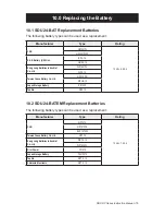
Страница 15: ...Industrial Co Ltd WP1221W WP5 12 Taiwan Yuasa Battery Co Ltd NP5 12 FR NPH5 12 Japan Storage Battery PE12V5 Toplite NP5 12 10 2 SDU 24 BATEM Replacement Batteries The following battery types can be u...

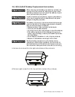
Страница 16: ...n working on batteries Remove watches rings and other metal objects Use tools with insulated handles Do not lay tools or other metal objects on top of the batteries If the battery replacement kit is d...

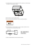
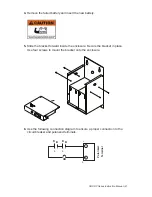
Страница 17: ...he battery posts 5 Remove the failed battery batteries Insert the new battery batteries 6 Use the following connection diagram to ensure a proper connection to the fuse protection board and polarized...

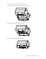
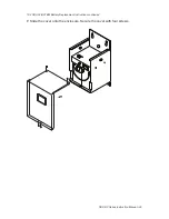
Страница 18: ...struction Manual 18 10 3 SDU 24 BAT Battery Replacement Instructions continued 8 Using four screws secure the protection fuse board 9 Slide the front cover onto the enclosure 10 Secure the assembly wi...

Страница 19: ...tions should be observed when working on batteries Remove watches rings and other metal objects Use tools with insulated handles Do not lay tools or other metal objects on top of the batteries If the...

Страница 20: ...anual 20 10 4 SDU 24 BATEM Battery Replacement Instructions continued 2 Remove the wires from the battery posts 3 Secure the bracket in place Remove four screws from the enclosure Slide the bracket fo...

Страница 21: ...ttery 5 Slide the bracket forward inside the enclosure Secure the bracket in place Use four screws to mount the bracket onto the enclosure 6 Use the following connection diagram to ensure a proper con...

Страница 22: ...SDU DC Series Instruction Manual 22 10 4 SDU 24 BATEM Battery Replacement Instructions continued 7 Slide the cover onto the enclosure Secure the cover with four screws...

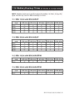
Страница 23: ...A 80 8 A 100 10 A 1 unit 113 45 30 21 14 2 units 247 114 74 48 38 3 units 396 178 117 80 58 4 units 531 233 148 111 81 11 2 SDU 20 24 with SDU 24 BAT Load 20 4 A 40 8 A 60 12 A 80 16 A 100 20 A 1 unit...

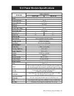
Страница 24: ...2 Maximum Elevation 3500 m 11 483 ft Shock Vibration According to ISTA 2A installation MTBF 200 000 hours Output Outputs are capable of providing high currents for short periods of time for inductive...

Страница 25: ...Sealed maintenance free lead acid batteries Enclosure Type IP20 NEMA 1 Terminal Connector Type Polarized powerpole connectors Operating Temperature 20 C to 50 C Charge Temperature 0 C to 40 C Storage...

Страница 26: ...voltage is too high too low or exceeds the specifications Adjust dc input voltage to an appro priate level Other failure Call SolaHD Technical Support Backup time is too short Battery is not fully ch...

Страница 27: ...re the ambient temperature is 20 C to 30 C 5 F to 86 F charge the UPS battery every 6 months During extended storage in environments where the ambient temperature is 30 C to 45 C 86 F to 113 F charge...

Страница 28: ...Part Number A272 134 Rev 6 September 9 2008 Technical Support U S 800 377 4384 International 847 268 6651 E mail www solahd com...

Отзывы: