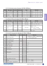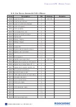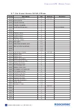
9. 10. U
Ps
E
nabLEd
c
ontroLs
t
abLE
: a
ddrEss
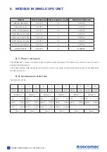
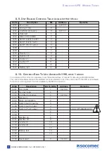
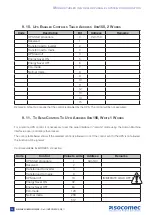
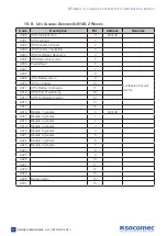
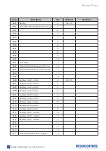
0
xm
150, 2 w
ords
code
description
Bit
address
Remarks
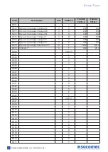
UPS Start procedure
0
0xm150
Reserved
1
Transfer load to inverter
2
Transfer load to mains
3
UPS load off
4
Energy Saver ON
5
Energy Saver OFF
6
Eco-mode
7
Normal mode
8
9
10
11
12
13
14
15
Remark: A bit set to 0 means that the control is disabled by the UPS. The control will be not executed.
9. 11. t
o
s
End
c
ontroL
t
o
U
Ps
: a
ddrEss
0
xm
190, w
ritE
1 w
ords
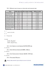
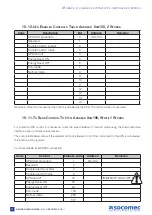
For a remote UPS control, it is necessary to set the serial interface in “remote” mode using the Human Machine
Interface. Local controls are then locked.
The control table below shows if the selected control is allowed or not. If the control sent to the UPS is not allowed,
the function will be ignored.
Controls available by MODBUS connection:
code
control
value to write
address
Remarks
UPS Start procedure
1
0xm190
Reserved
2
Transfer load to inverter
4
Transfer load to mains
8
UPS load off
16
immediate load oFF !!
Energy Saver ON
32
Energy Saver OFF
64
Eco-mode
128
Normal mode
256
512
m
odbUs
tables
In
modUlar
Parallel
system
confIgUratIon
26
Delphys green power
- Ref.: IOMDGPJB0910-GB_11
Содержание DELPHYS BC
Страница 47: ......

