Scope Multimeter
Operation and Controls
115
Trigger Auto/Manual Mode (Optional Setting)
NOTE
The Auto and Manual Trigger modes allow you to set the criteria used to
display signals on the screen. To change the trigger mode, the trigger must be
set on one of the channels.
In both Auto and Manual Trigger mode the screen is updated when the signal
crosses the trigger point in the selected direction (rising or falling), however:
•
Auto Trigger
—(default mode)
–
when Auto Trigger is on, even if the signal does not cross the trigger point,
the screen automatically updates after a short period (allowing you to see the
waveform). When this occurs, the message "Waiting for the trigger"
is displayed on the screen. The trigger point can then be set
to optimize viewing.
•
Manual Trigger
–
when Manual Trigger is on, if the signal does not cross the trigger point the
screen will not update. This allows you to capture intermittent events, as the
screen only updates when the signal meets your trigger selection.
NOTE
When using Manual Trigger, it may be easier to initially set the trigger point
using Auto Trigger, as the screen will update regardless if the signal crosses
the trigger point. Once the trigger point is set, then switch to Manual Trigger
mode.
z
Selecting Trigger Auto/Manual Mode:
1.
From the Control Panel (on the test meter screen), turn the trigger on for the
desired channel.
2.
Select the
Settings
icon from the toolbar.
3.
Select
Settings > Configure Scope / Meter > Trigger Mode
from the menu
selections.
4.
Select either
Auto Trigger
or
Manual Trigger
.
5.
Select
Back
or press the
N/X
button to navigate back to the test meter screen.
Threshold
NOTE
The Threshold function is only available in the Graphing Meter function for
specific tests. This function may also be referred to as Auto Threshold Select
(ATS).
The Threshold function can be used, to display and obtain a more accurate
measurement when measuring signals (e.g. Frequency, Duty Cycle, MC Dwell and
Pulse Width) that may be difficult to display or have noise or other undesirable
variations in the signal. When selected, the Threshold function automatically sets a
trigger and determines a threshold level in the middle of the signal range
(calculated from the Min and Max measurements) to be used as a reference point
to calculate the measurement. The falling edge (slope) of the signal is used in
determining the threshold level.
To activate the Threshold function, select the
Threshold
icon, then select
Continue
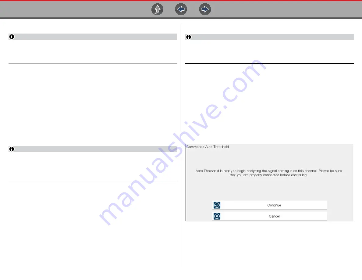
from the confirmation screen (
). Once selected, the
Threshold function remains active until the test is exited.
Figure 12-23
Auto Threshold Confirmation Screen
If after enabling the Threshold function, if the signal is still not displayed, reduce the
vertical scale setting. Sometimes a low frequency signal may not display if the
vertical scale is set too high. If the signal still seems incorrect use the lab scope to
verify the signal integrity and signal spacing. Slow or unequal spacing will display as
a band or ragged signal, depending on the sweep setting.


