SMC Networks LECP1 Series Скачать руководство пользователя страница 20


- 19 - 


6. CN4: Parallel I/O cable   

6.1 Paralles input / output 

■Input specifications   


          ■

Output specifications 


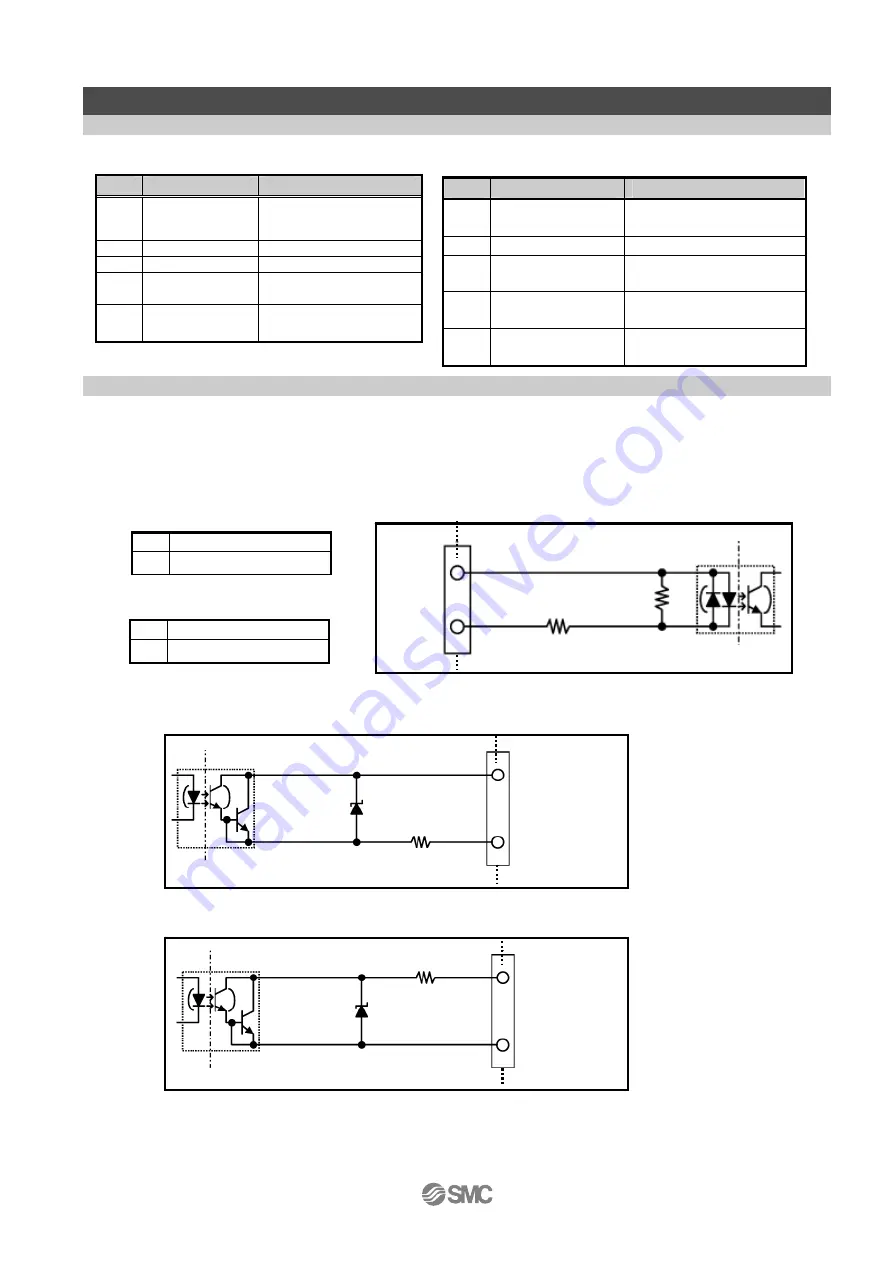
6.2 Parallel input / output circuit (NPN, PNP) 

There are two types of parallel input / output types for this controller. 

NPN type 

LECP1N

□□


PNP type 

LECP1P

□□


(1) Parallel I/O input circuit (NPN, PNP common) 


(2) Parallel I/O output circuit 


NO.

Item  

Specifications 

Output circuit 

Internal circuit and the 
photo coupler insulation 

No. of output 

6 opints 

Maximum voltage 
between terminals 

DC30V 

Maximum output 
current 

10mA 

Saturation voltage 
between terminals 

2.0V (Maximum) 

NO. 

Item  

Specifications 

1 Input 

circuit 

Internal circuit and the 
photo coupler insulation

No. of inputs 

6 points 

3 Voltage 

DC24V±10% 

Input current 
 at ON 

3.5mA±20%(at DC24V) 

Input current  /  
voltage at OFF 

1.5mA or less of current
11V or less of voltage 


(a)

(b)


Inside of the controller 

(a) 

COM+

」〈

1


(b)  IN0

9

〉~

STOP

14


 PNP TYPE  

(a) 

COM-

」〈

2


(b)  IN0

9

〉~

STOP

14


NPN TYPE   

PNP TYPE   

Outside 


OUT0

3


ALARM

8


OUT0

3


ALARM

8


COM-


2


COM+


1


Inside of the controller 

Outside 

Inside of the controller 

Outside 


 NPN TYPE  

Содержание LECP1 Series

Страница 1: ...Doc no LEC OM03901 PRODUCT NAME Programless controller Step motor servo 24 VDC MODEL Series LECP1 Series...

Страница 2: ...ly cable specification 17 1 Wiring of power supply 17 2 Wiring for the switch for forced unlocking 17 3 Wiring for the stop switch 17 4 Stop the power supply for the motor 18 6 CN4 Parallel I O cable...

Страница 3: ...able 8 to 20m 57 11 3 Actuator cable for sensor lock 5m or less 58 11 4 Actuator cable for sensor lock 8 to 20m 58 12 Alarm detection 59 12 1 Alarm group output 59 12 2 Alarm Content Countermeasure 60...

Страница 4: ...to its latest catalog information with a view to giving due consideration to any possibility of equipment failure when configuring the equipment 2 Only personnel with appropriate training should oper...

Страница 5: ...replacement parts Please consult your nearest sales branch For any failure or damage reported within the warranty period which is clearly our responsibility a replacement product or necessary parts w...

Страница 6: ...control power supply is on and parallel I O control is available Automatic sequence function of the returning to origin position Returning to origin position is available through I O signal combinatio...

Страница 7: ...3 3m 5 5m Power cable length is 1 5m only Controller I O cable length Actuator type Applicable actuators Electric gripper LEH Series Electric slide table LES Series Electric actuator Rod type LEY Seri...

Страница 8: ...ing the part number for an actuator set Warning Refer to 4 External connection P 15 for wiring Refer to 13 Wiring of cables Common precautions P 63 when handling the wiring and cables Electric actuato...

Страница 9: ...part number for an actuator set If parts are missing or damaged please contact our distributor 2 Mounting the Controller Refer to 3 4 Mounting P 13 to mount the controller 3 Controller Wiring Connecti...

Страница 10: ...ted Confirm the content of the alarm with 7 segment LED of the controller or I O output Eliminate the cause referring to 12 Alarm detection P 59 5 Data Operation pattern setting Set the stop position...

Страница 11: ...ent display red Figures are expressed in hexadecimal 10 to 15 in decimal number are expressed as A to F Locking With unlocking terminal Cable length I O cable 5m or less Actuator cable 20m or less Coo...

Страница 12: ...isplayed g SET Set button Decide the settings or drive operation in Manual mode h Position switch Assign the position to drive 1 to 14 and the origin position i Forward button Perform forward jog and...

Страница 13: ...ng position switch h and the set value of the speed acceleration switch k to n Size End width L 2 0 to 2 4 mm End thickness W 0 5 to 0 6 mm Magnified view of the end of the flat blade screwdriver 3 3...

Страница 14: ...cable as shown below Caution M4 screws cable with crimping terminal and serrated washer are prepared by customer Ground the controller to reduce noise Mounting screw LECP1 Mounting with two M4 screws...

Страница 15: ...ed Keep enough space around the controller so that the operating temperature of the controller stays within the specification range Avoid mounting on a panel where a vibration source such as large siz...

Страница 16: ...r CN3 Encoder connector Connect the controller and the actuator with the actuator cable LE CP or LE CP S 4 3 CN4 Parallel I O connector Refer to 6 4 Parallel I O connector wiring Example P 22 for wiri...

Страница 17: ...th L LEC CK1 1 1 5m only Termin al Color of covered wire Function Functional explanation 0V Blue Common power supply Common for motor supply controller supply and brake release M24V White Power supply...

Страница 18: ...ing for the switch for forced unlocking Install unlocking switch for the adjustment or recovery during emergency of the locking actuator Switch 24V DC contact capacity 0 5A or more is provided by cust...

Страница 19: ...to origin position neither drive operation when the the power supply for the motor M24V is shut off otherwise alarm will be generated The controller does not recognize the correct origin position with...

Страница 20: ...tput 6 opints 3 Maximum voltage between terminals DC30V 4 Maximum output current 10mA 5 Saturation voltage between terminals 2 0V Maximum NO Item Specifications 1 Input circuit Internal circuit and th...

Страница 21: ...UT3 OUT2 OUT1 OUT0 OFF OFF ON ON 7 Gray Black BUSY BUSY signal Output during operation 8 Gray Red ALARM ALARM signal N C Turned off during alarm or when servo is turned off 9 White Black IN0 10 White...

Страница 22: ...tion positioning and pushing operation 1 1 1 1 OFF ON Stopped by RESET command OFF OFF OFF OFF OFF ON Stopped by STOP command OFF OFF OFF OFF OFF OFF When alarm is generated OFF 2 2 2 OFF OFF 1 ON OFF...

Страница 23: ...ease wire the product referring to the wiring diagram NPN TYPE PNP TYPE Caution Prepare separate 24VDC power supplies for the CN1 controller input power supply and CN4 input output signal power supply...

Страница 24: ...he mode to avoid unexpected mode changes Manual mode M Auto mode A Setting of stop position step data O X Setting of Speed and Acceleration O Only in speed adjustment 2 Setting of operation method O X...

Страница 25: ...15 then press the set button g to start the return to origin When the return to origin is completed the display of the 7 segment LED f changes changes from flashing to solid Caution If you perform ret...

Страница 26: ...et button makes the LED flash slowly Release the set button g If you release the set button g the operation stops in the middle If you release the set button g in the middle of the operation press the...

Страница 27: ...ration method of this position by pressing Forward button i or Reverse button j monitoring 7 segment LED f Actual force of pushing force depends on the actuator Refer to 10 Initial setting value per a...

Страница 28: ...servo is turned on Power supply LED a lights up in green alarm is generated Perform jog inching after confirming that the servo is turned on Set operation method per position number Refer to 8 Operati...

Страница 29: ...g solid lighting slow flashing 4 Move the actuator to desired position with external force Lock in the position by pressing the set button g At this point the position is not stored If the power suppl...

Страница 30: ...the setting by direct teaching If you continue to set other position start from the procedure 2 If you perform setting with Jog Inching or test run press Forward button i and Reverse button j for 3 s...

Страница 31: ...tion with the same operation For Pushing operation check with the test function of manual mode or auto mode Refer to 7 4 Test function P 38 for details of normal operation and test function 7 Setting...

Страница 32: ...t value of position switch 2 Press the Forward button i and Reverse button j simultaneously for 3 sec and the power supply LED a will flash 3 When you set the position switch h at 0 and press the set...

Страница 33: ...everse 2 Jog speed level Adjust the jog speed 3 Inching level Adjustment of inching 5 The 7 segment LED f indication is turned off by pressing the set button g and the current parameter appears 1 appe...

Страница 34: ...rigin and forward and reverse 1 CW Default value of LEF and LEH series at the time of shipment 2 CCW Dafault value of LES and LEY series at the time of shipment Jog speed level 2 Adjust the jog speed...

Страница 35: ...not output from I O right after switching from manual mode to auto mode Output from I O is made after the next input of operation command Output from I O is not made if switching from auto mode to ma...

Страница 36: ...side Mode switch e is on auto side Before retuning to origin position After retuning to origin position PLC commands to return to origin Command from the controller to return to origin position Positi...

Страница 37: ...eed acceleration switch values which are set by k to n do not take effect except during the speed adjustment status If returning to auto mode after changing to manual mode the value of the switch affe...

Страница 38: ...sing manual button i j Press the set button g for 2sec Press the set button g for 2 sec Operation completed Adjusting the operation method by pushing manual button i j Set the position switch h to 15...

Страница 39: ...pushing operation X O Operation by parallel I O input X X Output to parallel I O X O 7 segment LED f display Without dot Target position setting Quick flashing During operation Slow flashing Reached t...

Страница 40: ...power was supplied Origin position depends on the actuator 1 in the figure below The controller recognizes the actuator end when the slider travels to the actuator end and stops for specific time The...

Страница 41: ...ual mode positioning is performed even if pushing is set Except during test function Pushing operation may not be possible depending on the actuator Refer to 10 Initial setting value per actuator P 48...

Страница 42: ...e pushing move is completed the actuator is pushed until the reaction force and pushing force are balanced in the direction that the pushing started Completion signal stays ON An alarm is generated wh...

Страница 43: ...button for 1sec or longer after inching jog operation starts Jog operation stops when the button is released Caution The travel amount of inching and jog speed depend on actuators Refer to 10 Initial...

Страница 44: ...ains following factors 1 Controller input signal scan delay 2 Delay due to input signal analysis 3 Delay of command analysis Process delay of PLC or scanning delay of the controller may occur Keep the...

Страница 45: ...the power and the ALARM turns on 2 Confirming that the ALARM turned on turn on IN0 to 3 to perform 1 Return to origin 3 When return to origin starts BUSY turns on 4 Turn OFF IN0 to 3 after confirming...

Страница 46: ...BUSY turns ON when the operation starts and OUT0 and 1 turn OFF 3 When BUSY turns ON turn OFF IN2 4 BUSY turns OFF when the operation is completed and OUT2 turns ON 5 Do the same for the travel for po...

Страница 47: ...RESET during operation 5 Stops by reducing speed BUSY turns OFF 6 When BUSY turns OFF turn OFF RESET 7 Turn ON IN3 to start travel to position No 8 8 When the operation starts BUSY turns on 9 When BUS...

Страница 48: ...RESET after troubleshooting the alarm 6 Alarm is deactivated ALARM is turned OFF 7 When ALARM turns OFF turn OFF RESET 8 Turn ON IN0 1 3 Then start the operation 2 to position No 11 9 When the operat...

Страница 49: ...e 7 segment LED f of the controller it becomes positioning Refer to the table below for the speed and the acceleration table of the LEFB series LEFB16 LEFB25 LEFB32 Speed mm s Acceleration mm s2 Speed...

Страница 50: ...0 8 150 1000 75 1000 150 1000 75 1000 9 200 1200 100 1200 200 1200 100 1200 10 250 1400 125 1400 250 1400 125 1400 11 300 1600 150 1600 300 1600 150 1600 12 350 1800 175 1800 350 1800 175 1800 13 400...

Страница 51: ...the table below for the set value for 3 levels of pushing force of the LEHZ series Pushing speed is fixed to 5mm s LEHS10 LEHS20 Basic Compact Basic Compact LEHS 32 LEHS 40 Low 2 2 1 4 9 7 36 52 Midd...

Страница 52: ...0 1600 80 1600 80 1600 80 1600 14 75 1800 90 1800 90 1800 90 1800 15 80 2000 100 2000 100 2000 100 2000 Refer to the table below for the speed acceleration of LEHS series LEHS10 LEHS20 LEHS32 LEHS40 s...

Страница 53: ...0 40 700 40 700 8 45 800 45 800 45 800 45 800 9 50 900 50 900 50 900 50 900 10 55 1000 55 1000 55 1000 55 1000 11 60 1200 60 1200 60 1200 60 1200 12 65 1400 65 1400 70 1400 70 1400 13 70 1600 70 1600...

Страница 54: ...the operation manual of the actuator for details Refer to the table below for the speed and the acceleration table of the LES series LESH8 16RJ LESH8 16RK LESH25RJ LESH25RK speed mm s acceleration mm...

Страница 55: ...g force N High 38 74 141 122 238 452 189 370 707 Pushing speed mm s 15 8 4 18 9 5 24 12 6 Pushing force accuracy is 20 F S Refer to the operation manual of the actuator for details Refer to the table...

Страница 56: ...00 88 1800 13 400 2000 200 2000 100 2000 14 450 2500 225 2500 113 2500 15 500 3000 250 3000 125 3000 LEY32A LEY32B LEY32C speed mm s acceleration mm s2 speed mm s acceleration mm s2 speed mm s acceler...

Страница 57: ...ss of the 3 levels Pushing speed LER K is 20 s Fixed LER J is 30 s Fixed LER10 LER30 LER50 K J K J K J Pushing torque N m 0 15 0 1 0 6 0 4 5 0 3 3 Pushing torque accuracy LER10 30 F S LER30 25 F S LER...

Страница 58: ...ller side Cable length L 1 1 5m 3 3m 5 5m Cable length L 8 8m A 10m B 15m C 20m Signal TerminalNo A B 1 A A 1 B B 2 B A 2 COM A COM B 3 COM B A 3 Vcc B 4 GND A 4 A B 5 A A 5 B B 6 B A 6 Cable color Te...

Страница 59: ...minalNo Lock B 1 Lock A 1 Sensor B 3 Sensor A 3 Cable length L 8 8m A 10m B 15m C 20m L 14 2 17 7 11 30 7 14 18 B1 A1 A6 B6 5 2 2 1 15 16 6 1 Actuator side Controller side B1 A1 B3 A3 10 2 5 5 5 7 6 3...

Страница 60: ...the LED and the signal is output from I O so that the alarm type is recognizable For alarms LED b lights up in red and the alarm group is indicated by the 7 segment LED f The I O indicates the presen...

Страница 61: ...tion This is generated when return to origin positioning pushing or a jog operation is commanded when the servo is OFF C Stopped Input RESET Countermeasure Check if I O signal STOP is input Also check...

Страница 62: ...in the controller is high D Any condition Input RESET Countermeasure Improve the peripheral environment of the controller after checking the installation of the controller Refer to 3 4 Mounting P 13...

Страница 63: ...n Position deviation counter in the controller has overflowed E During operation Power supply for control is turned off Countermeasure Check if the travel of the actuator is interrupted Check if the l...

Страница 64: ...s at sharp angles where they enter the product 7 Avoid twisting folding rotating or applying an external force to the cable Risk of electric shock wire break contact failure and lost of control for th...

Страница 65: ...ign the system so that human injury and or damage to machinery and equipment will not be caused when it is stopped by a safety device for abnormal conditions such as a power outage or a manual emergen...

Страница 66: ...to precise tolerances so that even a slight deformation may cause faulty operation 6 Prevent the seizure of rotating parts Prevent the seizure of rotating parts pins etc by applying grease 7 Do not u...

Страница 67: ...d with a different parameter failure can result 2 Check the product for the following points before operation a Damage to electric driving line and signal lines b Looseness of the connector to each po...

Страница 68: ...rs such as dust cutting chips and spatter Play or increased sliding resistance can result 4 Shade the sunlight in the place where the product is applied with direct sunshine 5 Shield the valve from ra...

Страница 69: ...pact load or strong vibration while the lock is activated If an external impact load or strong vibration is applied to the product the lock will lose it s holding force and damage to the sliding part...

Страница 70: ...electric shock or damage to the controller 2 Do not perform the operation or setting of this equipment with wet hands It may cause an electric shock 3 Product with damage or the one lacking of any com...

Страница 71: ...er and its peripheral devices together with a large sized electromagnetic contactor or no fuse breaker which generates vibration on the same panel Mount them on different panels or keep the controller...

Страница 72: ...100 or less 3 Grounding should be performed near the unit as much as possible to shorten the grounding distance 4 In the unlikely event that malfunction is caused by the ground it may be disconnected...

Страница 73: ...to the operation manual of the controller to check wiring for broken wires and short circuits Correct wiring and check if the input output of each signal is correct Prepare separate power supply for...

Страница 74: ...asures against noise Ground properly Avoid bundling the cables Refer to the operation manual of the controller 3 4 Mounting P 13 Voltage drop Temporary voltage drop in the power supply Possibility of...

Страница 75: ...nnection P 15 6 4 Parallel I O connector wiring Example P 22 Doesn t move to the correct position Unsuitable specification Check if a product with a suitable specification was selected Reconfirm the c...

Страница 76: ...1 Sotokanda Chiyoda ku Tokyo 101 0021 JAPAN Tel 81 3 5207 8249 Fax 81 3 5298 5362 URL http www smcworld com Note Specifications are subject to change without prior notice and any obligation on the par...

Отзывы: