background image

HRX-OM-Q026-B 

Chapter 7   Control, Inspection and Cleaning 


HRSH Series 

7.3

 Consumables 


7-5

7.2.4 

Inspection for winter season 


„


Anti-freezing function 

To prevent the circulating fluid freezing during winter, this function operates 
pump automatically to heat the circulating fluid by the pump’s heat radiation. If 
there is a possibility of the circulating fluid freezing due to changes in the 
installation and operating environment (season and weather), set this function in 
advance.


For details, refer to “5.10


Anti-freezing function”. 


„


Warming up function 

During winter or night, this function operates pump automatically to heat the 
circulating fluid by the pump’s heat radiation to keep the circulating fluid 
temperature around the warming up function set temperature. If it is necessary to 
shorten the circulating fluid temperature rising time, set this function in advance. 

For details, refer to “5.17 Warming up function”. 


„


Anti-snow coverage function 

To prevent the snow coverage on the ventilation air outlet of the fan in winter, this 
function operates fan automatically. If there is a possibility of the snow coverage 
due to changes in the installation and operating environment (season and 
weather), set this function in advance. 

For the details, refer to “5.18Warming up function”. 


7.3 Consumables 

Replace the following parts depending on their condition. 
  

Table 7-3 Consumables 

Part number 

Name 

Qty. 

Remarks 

HRS-S0213 

Dust-proof filter 

(Upper) 

1 piece 

HRSH150/200

2 pieces are used per unit

HRS-S0214 

Dust-proof filter 

(Lower) 

1 piece 

HRSH150/200

2 pieces are used per unit

HRS-S0185 

Dust-proof filter 

1 piece 

HRSH250

4 pieces are used per unit 


The power supply should be ON for these functions. Otherwise these 
functions cannot start.


Содержание HRSH150-A*-20 Series

Страница 1: ...B Mar 2013 Operation Manual Installation Operation Original Instructions Thermo chiller HRSH series HRSH150 A 20 HRSH200 A 20 HRSH250 A 20 HRSH250 A 40 Keep this manual available whenever necessary 20...

Страница 2: ...ion and operation of the product Only people who understand the basic operation of the product through this manual or who perform installation and operation of or have basic knowledge about industrial...

Страница 3: ...roduct 2 1 2 2 Name and Function of Parts 2 2 2 3 Function of Parts 2 3 2 4 Operation display panel 2 4 Chapter 3 Transport and Setting Up 3 1 3 1 Transport 3 1 3 1 1 Moving by forklift and slinging 3...

Страница 4: ...6 Adjustment of Circulating Fluid flow rate 4 9 Chapter 5 Display and setting of various functions 5 1 5 1 Function 5 2 5 1 1 Key operations 5 2 5 1 2 List of parameters 5 4 5 2 Main screen 5 7 5 2 1...

Страница 5: ...32 5 14 Data reset function 5 33 5 14 1 Data reset function 5 33 5 14 2 Method of resetting data reset function 5 33 5 15 Accumulated time reset function 5 34 5 15 1 Accumulated time reset function 5...

Страница 6: ...2 2 Monthly check 7 3 7 2 3 Inspection every 3 months 7 4 7 2 4 Inspection for winter season 7 5 7 3 Consumables 7 5 7 4 Stop for a Long Time 7 6 7 4 1 Discharge of the circulating fluid and facility...

Страница 7: ...HRX OM Q026 B Contents HRSH Series Chapter 9 Product Warranty 9 1...

Страница 8: ......

Страница 9: ...e If a component needs to be replaced or repaired contact a specialized vendor for parts and service z All personnel who work with or around the product should read and understand the safety related i...

Страница 10: ...ing to severity DANGER WARNING CAUTION 1 3 2 Definition of Serious injury and Minor injury Serious injury This term describes injuries that result in after effects including loss of eyesight burns ele...

Страница 11: ...when contacting an SMC sales distributor How to see the serial number Q Z 001 December 2012 O O 001 Year Symbol Remarks Month Symbol Remarks Serial no 2012 Q 1 O 2013 R 2 P 2014 S 3 Q Repeated from A...

Страница 12: ...itted correctly and securely after maintenance z Avoid working in a drunken or sick condition which might cause an accident z Do not remove the panels except for the cases permitted in this manual z D...

Страница 13: ...of the product must be handled by a specialized industrial waste disposal agency in accordance with local laws and regulations z Only maintenance personnel or qualified people are allowed to open the...

Страница 14: ...al Safety Data Sheet MSDS HRSH Series 1 6 1 8 Material Safety Data Sheet MSDS If the material safety data sheets of chemicals used in this product are needed contact an SMC s sales distributor Any che...

Страница 15: ...led refrigeration None Nill Earth leakage breaker Fluid fill port B 1 K 2 2 Manual fluid fill port that is different from the automatic fluid fill function This enables that circulating fluid can be f...

Страница 16: ...r set HRS EP013 1set Circulating fluid outlet port Rc1 Circulating fluid return port Rc1 Automatic fluid fill port Rc1 2 Overflow port Rc1 Signal cable entry Grommet with membrane Tank drain port Rc3...

Страница 17: ...lter Inserted to prevent that the dust and contamination are clung on the air cooled condensers directly For details prefer to 7 2 2Monthly check Power cable entry Power terminal Insert the power cabl...

Страница 18: ...rval 2 seconds At operation Interval 0 3 seconds Blinks during warming up function At standby lit on for 0 5 seconds and off for 3 seconds At operation interval 0 3 seconds 4 4 Flashes with buzzer whe...

Страница 19: ...ence about the product and system are allowed to transport and set up the product z Especially pay attention to personal safety Never lay the product on its side The compressor oil will leak in to the...

Страница 20: ...forklift and slinging Fig 3 1 Fork insert and slinging position The wights of the product are HRSH150 200 Approx 215kg HRSH250 Approx 280kg Moving by forklift and slinging should be done by persons w...

Страница 21: ...the product Fig 3 2 Transportation using casters Do not hold the piping connections and grips of the panels when moving by casters It may cause a damage to the product Push the corners of the product...

Страница 22: ...nside electrical parts z Location that is near heat sources and poor in ventilation z Location that is subjected to abrupt changes in temperature zLocation that is subjected to strong electromagnetic...

Страница 23: ...port In case of using at altitudes of 1000m or higher please contact us z Location where the product is affected by strong vibrations or impacts zCondition that applies external force or weight causin...

Страница 24: ...utlet ventilation of the product directly Have the space at least the dust s diameter apart Use a fan for the duct that considered the ventilation resistance of the duct Table 3 1 Amount of radiation...

Страница 25: ...d Maintenance Space It is recommended to keep the space around the product shown in Fig 3 3 Fig 3 3 Installation space Have an enough space for the ventilation for the product Otherwise it may cause a...

Страница 26: ...oundations bolt set IDF AB500 SUS M10x50mm is applicable Fig 3 4 Installation procedures Install the product on the horizontal floor Prepare the M10 anchor bolts that are appropriate to the material o...

Страница 27: ...Fig 3 5 Installation by adjuster foot In case of using Caster Adjuster foot kit be sure to use the adjuster foot to install on the floor The adjuster foot is not earthquake proof Make an earthquake r...

Страница 28: ...the terminals Incomplete wiring or improper securing of wiring may cause electrical shock excessive heat and fire z Ensure a stable power supply with no voltage surges z Ensure that an Earth Leakage...

Страница 29: ...5mm2 3xAWG10 HRSH250 A 40 AC380 415V 50 60Hz 3phase M5 R14 5 For ground line 1x14mm2 1xAWG6 For ground line 30 30 1 A specified earth leakage breaker is installed for option B Earth leakage breaker of...

Страница 30: ...the panel is removed or mouted be sure to wear protective shoes and gloves to prevent injury with the edge of the panel A breaker that has the operating characteristic below is installed Please use a...

Страница 31: ...Remove the front panel for the electrical unit 2 Hold the handle and put up the front panel of the electrical unit and remove it Fig 3 7 Remove the front panel of the electrical unit Handle A Screw Fr...

Страница 32: ...as shown in the figure below Fig 3 8 Wiring of power supply cable Connect over current protection to the power cable connected to the equipment in order to avoid hazard Inlet of the power supply cabl...

Страница 33: ...block screw diameter Crimp terminal Cable specification M3 1 25Y 3 0 75 mm2 AWG18 Shielded cable 3 3 5 Wiring of Run stop signal input Remote signal input Run stop signal input Remote signal input en...

Страница 34: ...f contact output signal 2 Run stop signal input Remote signal input External switch signal input 2 Switch the input on the operation display panel Refer to the operation manual communication function...

Страница 35: ...o the terminal as follows This wiring is an example Fig 3 9 Wiring of Run stop signal input Remote signal input Example Inlet of the signal cable Note Prepare a cable tie Fasten the signal cable to th...

Страница 36: ...n total The external switch cannot be connected to the contact input signal 1 depending on the communication mode Table3 7 External switches used in examples Table 3 6 Sets external switch Communicati...

Страница 37: ...repare the flow switch described in the table purchasing separately 2 Depending on the external switch output type wire the switch to the terminals for contact input signal as shown below This is an e...

Страница 38: ...Category Communication mode LOC LOC Contact input signal 1 RUN SW_A Contact input signal 1 type ALT ALT Contact input signal 1 delay timer time delay of reading 0 0 Contact input signal 1 OFF detectio...

Страница 39: ...open At generation Contact open Not generated Contact closed Contact output signal 3 Terminal no 2 10 Alarm status signal output B With power supply shut off Contact open Tips This product has three o...

Страница 40: ...w for connecting multiple thermo chillers z Configuration of connection One host computer One thermo chiller or one host computer N thermo chillers Max 31 thermo chillers can be connected 1 SD 5 SG 9...

Страница 41: ...of alarm condition can be done by remote control Refer to the Communications Operation Manual for more details Wiring of communication cable Be sure to wire as shown in the figure below z Configuratio...

Страница 42: ...ore Tips In case of HRSH N A set of thread adapters that converts the connections from Rc to NPT is enclosed as an accessory Be sure to use this for NPT piping In case of HRSH F A set of thread adapte...

Страница 43: ...ig 3 15 Connection to the drain Tank drain port Hold the ball valve Without holding the ball valve of the drain port with a wrench the ball valve may rotate and it may cause a fluid leakage and malfun...

Страница 44: ...fluid outlet port Circulating fluid return port Overflow port Drain port To sump pit Fluid supply Customer s system 1 2 2 2 1 2 4 3 5 Fig 3 16 Recommended piping circuit No Name Size 1 Valve Rc1 2 2 V...

Страница 45: ...d or the ambient temperature is lower than 10 deg C use 15 aqueous solution of ethylene glycol Otherwise it may cause icing of the fluid z Confirm that the fluid level is between HIGH and LOW level of...

Страница 46: ...matic fluid fill port Rc1 2 Supply pressure 0 2 0 5MPa Overflow port Rc1 Should be ID25mm and more length 5m and less and avoid riser piping trapping part Fig 3 18 Piping of the automatic fluid fill p...

Страница 47: ...ort on the tank removing the right side panel upper 1 Remove the screws 6 places to remove the right side panel upper Fig 3 19 Removing the screws 2 Hold the handle and put up the right side panel upp...

Страница 48: ...el of the fluid level gauge Fig 3 21 Filling the fluid to the fluid fill port An example z Check the drain port is closed by the valve to prevent the supplied circulating fluid from draining out z Con...

Страница 49: ...uid up to the level between the HIGH and LOW of the fluid level gauge Fig 3 22 Filling the fluid to the fluid fill port An example z Confirm that the fluid level is between HIGH and LOW level of the f...

Страница 50: ...HRX OM Q026 B Chapter 3 Transport and Setting Up 3 5 Fill of circulating fluid HRSH Series 3 32...

Страница 51: ...ion of cables z Check the power ground and communications optional cables are correctly connected Circulating fluid z Check proper connection of piping at inlet and outlet Automatic fluid filling pipi...

Страница 52: ...utlet temperature z The set value of circulating fluid temperature is displayed as SV on the panel z The present value of circulating fluid temperature is displayed as PV on the panel 4 2 2 For the op...

Страница 53: ...ss the and buttons on the operational panel to change the SV to required value When the temperature of the circulating fluid is set by the communication refer to Communication in the supplementary ope...

Страница 54: ...es independently while the PUMP key is pressed The RUN lamp green flashes while the pump is operating independently and the circulating fluid in the tank is supplied to the customer s device and pipin...

Страница 55: ...After the fluid is supplied more than LOW level the alarm can be reset Refer to clause 4 For the option K Fluid fill port Fill the circulating fluid to the fluid fill port up to the level between HIG...

Страница 56: ...d temp Circulating fluid set temp Press the PUMP key press RUN STOP key and MENU key simultaneously to start independent operation of the pump Fig 4 7 Alarm release 5 Repeat steps 1 to 4 to supply the...

Страница 57: ...ns on refer to Chapter 6 Alarm indication and trouble shooting 1 Press the RUN STOP key on the operation panel The RUN lamp lights up in green and the product starts running The circulating discharge...

Страница 58: ...rwise it may cause a failure 4 4 2 Stopping the product 1 Press the RUN STOP button on the operation panel The RUN lamp on the operation panel flashes green at 1 second intervals and continues operati...

Страница 59: ...range 4 6 Adjustment of Circulating Fluid flow rate Circulating fluid flow rate adjustment If the flow rate is lower than HRSH150 200 25L min HRSH250 40L min the performances may not be able to achie...

Страница 60: ...HRX OM Q026 B Chapter 4 Starting the Product 4 6 Adjustment of Circulating Fluid flow rate HRSH Series 4 10...

Страница 61: ...on automatically after the power supply is turned on 5 9 9 Key click sound setting Operation panel key sound can be set on off 5 11 10 Changing temp unit Temperature unit can be changed Centigrade o C...

Страница 62: ...ffset mode Offset temperature Recovery from power failure Anti freezing function Data reset Pump accumulated operating time reset Fun accumulated operating time reset Compressor accumulated operating...

Страница 63: ...Simple communicatio n protocol Contact input signal 1 Contact input signal 1 type Contact input signal 2 Contact input signal 2 type Contact output signal 1 function Contact output signal 1 operation...

Страница 64: ...Pressure of lower pressure refrigerant circuit Unused Accumulated operation time of the pump Accumulated operation time of the fun Accumulated operation time of the compressor Accumulated operation ti...

Страница 65: ...rculating fluid discharge temperature drop 1 0 o C 33 8 F 7 Changing of circulating fluid discharge pressure rise A STP Detection pressure for circulating fluid discharge pressure rise 1 00MPa 145PSI...

Страница 66: ...8 Response delay time 0 8 Serial communication Simple communication protocol Communication range RW 8 Contact input signal 1 RUN Contact input signal 1 type ALT Contact input signal 1 delay timer tim...

Страница 67: ...rrent temperature and set temperature are displayed on the digital display Alarm display screen See 5 3 appears when an alarm is generated PV SV Circulating fluid temperature Set 2 Change the set temp...

Страница 68: ...ms 5 3 2 Content of display of alarm display menu The alarm display screen appears when an alarm is generated When multiple alarms are generated the latest alarm is displayed on the screen Each time t...

Страница 69: ...ssure at the outlet Pressure of higher pressure refrigerant circuit Displays the pressure of higher pressure side of the refrigerant circuit Pressure of lower pressure refrigerant circuit Displays the...

Страница 70: ...refrigerant circuit compressor inlet is displayed on the digital display PV SV Displays the temperature of the compressor inlet Check of the circulating fluid outlet pressure 4 Press the SEL key once...

Страница 71: ...ump Refer to the table below for the display Table 5 4 2 List of time display Cumulative time Indicated value 0h to 999h to 1 000h to 99 999h to 100 000h Return to AL28 Pump maintenance alarm is gener...

Страница 72: ...hapter 6 Alarm indication and trouble shooting Check of the accumulated operation time 10 Press the SEL key once The accumulated operation time is displayed on the digital display PV SV Displays the a...

Страница 73: ...nged by operator error Operation can be started stopped by the RUN STOP key even while key lock is set If you try to change the set value with and key while key lock is set is displayed for 1 sec on t...

Страница 74: ...setting is available OFF 1 Press and hold the MENU key for approx 2 sec Repeat pressing until the setting display for key lock setting appears on the digital display PV SV PV SV PV SV Key lock settin...

Страница 75: ...e this function does not operate DIO REMOTE SERIAL mode operation stop signal has priority Run timer Run timer starts operation after the set time If the thermo chiller is already operating or the pum...

Страница 76: ...topped Run timer Stop timer Set to start after 2 hours Set to stop after 5 5 hours Operating Stopped Now 1H 2H 3H 4H 5H 6H 7H 8H Operating Stopped Operating Run timer Stop timer Set to stop after 2 ho...

Страница 77: ...ase refer to the applicable items for the timer you wish to use 1 Press and hold the MENU key for approx 2 sec Repeat pressing the key until the setting screen for key lock appears on the digital disp...

Страница 78: ...t of set value Set value Explanation Initial value Default setting Timer OFF to Operation stops after set time Setting unit is 0 5 hour E g Set at 4 30pm Operation stops 1 hour and 30 minutes later at...

Страница 79: ...ontact input output and serial communication is used Refer to the Communications Operation Manual for more details An example is shown below Circulating fluid set temperature 20 o C READY band width u...

Страница 80: ...ets time of ready completion TEMP READY signal 1 Press and hold the MENU key for approx 2 sec Repeat pressing the key until the setting screen for key lock appears on the digital display PV SV PV SV P...

Страница 81: ...e range for the circulating fluid temperature Temperature unit is Centigrade Setting unit is 0 1o C Temperature unit is Fahrenheit Setting unit is 0 1o F READY time Set and checking 6 Press the SEL ke...

Страница 82: ...g sending of the fluid Circulating fluid display temperature 30 Circulating fluid set temperature 30 This produuct Your system Serial communication Discharge temperature 30 Heat radiation 1 29 Circula...

Страница 83: ...rge temperature offset temperature and matches the circulating fluid temperature of the customer s device Circulating fluid display temperature 29 Circulating fluid set temperature 30 Offset temperatu...

Страница 84: ...t temperature 0 0 o C 1 Press and hold the MENU key for approx 2 sec Repeat pressing the key until the setting screen for key lock appears on the digital display PV SV PV SV PV SV Offset mode Setting...

Страница 85: ...ng is OFF Centigrade to Fahrenheit to Sets offset temperature Temperature unit is Centigrade Setting unit is 0 1o C Temperature unit is Fahrenheit Setting unit is 0 1o F 6 Press the MENU key once Retu...

Страница 86: ...r failure etc this function restarts the operation when the power supply recovers retaining the conditions before the power cut When communication is used If the communication mode is DIO REMOTE SERIA...

Страница 87: ...prox 2 sec Repeat pressing the key until the setting screen for key lock appears on the digital display PV SV PV SV PV SV Recover from power failure Setting and checking 2 Press the SEL key 8 times Th...

Страница 88: ...mp does not operate The RUN lamp blinks every 0 3sec during the automatic operation of the pump The default setting of this function is OFF This function cannot prevent the freezing of the auto fluid...

Страница 89: ...Repeat pressing the key until the setting screen for key lock appears on the digital display PV SV PV SV PV SV Anti freezing function Setting and checking 2 Press the SEL key 9 times The set screen o...

Страница 90: ...t setting Key click sound Sets key click sound ON 1 Press and hold the MENU key for approx 2 sec Repeat pressing the key until the setting screen for key lock appears on the digital display PV SV PV S...

Страница 91: ...Item Contents Initial value Default setting Temperature unit Sets temperature unit o C 1 Press and hold the MENU key for approx 2 sec Repeat pressing the key until the setting screen for key lock app...

Страница 92: ...ontents Initial value Default setting Pressure unit Sets pressure unit MPa 1 Press and hold the MENU key for approx 2 sec Repeat pressing the key until the setting screen for key lock appears on the d...

Страница 93: ...mulated operation time is not reset NO 1 Press and hold the MENU key for approx 2 sec Repeat pressing the key until the setting screen for key lock appears on the digital display PV SV PV SV PV SV Dat...

Страница 94: ...ection service 5 15 2 Method of resetting accumulated time reset function The table below explains the setting items of the accumulated time reset and the initial values Table 5 15 1 List of set accum...

Страница 95: ...ial value Default setting Not reset Pump accumulated operating time is reset Fun accumulated operating time reset 4 Press the SEL key once The set screen of fun accumulated operating time reset is dis...

Страница 96: ...ter accumulated operating time reset 8 Press the SEL key once The set screen of dust proof filter accumulated operating time reset is displayed on the digital display PV SV 9 Select from the table bel...

Страница 97: ...ssure does not lower to the set pressure In this case the pressure cannot lower due to the large piping resistance even though the pump discharges the minimum flow This situation is not malfunction of...

Страница 98: ...key 23 times The set screen of pump operation mode is displayed on the digital display PV SV 3 Select the pump operation mode from the table below with key or key and confirm by pressing SEL Table 5 1...

Страница 99: ...tting unit is 0 1MPa Pressure unit is PSI Setting unit is 1PSI Pump operation frequency 6 Press the SEL key once The set screen of pump operation frequency is displayed on the digital display PV SV 7...

Страница 100: ...lit on for 0 5 sec and off for 3sec during standing by When the pump does not operate The RUN lamp blinks every 0 3sec during the automatic operation of the pump The default setting of this function i...

Страница 101: ...he key until the setting screen for key lock appears on the digital display PV SV PV SV PV SV Warming up setting and checking 2 Press the SEL key 26 times The set screen of warming up is displayed on...

Страница 102: ...set value Set value Explanation Initial value Default setting Setting checking are not available if the setting of the warming up function is OFF Centigrade to Fahrenheit to Sets the warming up set t...

Страница 103: ...eed for 1 minute and the normal controlled speed 29 minutes During the product stoppage Repeats the fan operation with the maximum speed for 1 minute and stoppage for 29 minutes The product operation...

Страница 104: ...prox 2 sec Repeat pressing the key until the setting screen for key lock appears on the digital display PV SV PV SV PV SV Anti snow coverage Setting and checking 2 Press the SEL key 28 times The set s...

Страница 105: ...Display Item Contents Initial value Default setting Alarm buzzer sound Sets alarm buzzer sound ON 1 Press and hold the MENU key for approx 2 sec Repeat pressing the key until the setting screen for al...

Страница 106: ...coverage function is ON the fan will rotate as mentioned in 5 18 Anti snow coverage function 2 The alarm operations of all the object alarms of the P RUN cannot be customized individually but collecti...

Страница 107: ...ting return temp Set pressure AL08 Circulating fluid discharge pressure rise 1 00MPa 145PSI 7 0 05 to 1 00MPa 7 145PSI Set pressure AL09 Circulating fluid discharge pressure drop 0 05MPa 7PSI 8 0 05 t...

Страница 108: ...rror AL21 DC line fuse cut AL22 Circulating fluid discharge temp sensor failure AL23 Circulating fluid return temp sensor failure AL24 Compressor suction temp sensor failure AL25 Circulating fluid dis...

Страница 109: ...9 Internal unit fan stoppage AL40 Dust proof filter maintenance AL41 Power stoppage AL42 Compressor waiting AL43 Fan breaker trip AL44 Fan inverter error AL45 Compressor breaker trip AL46 Compressor i...

Страница 110: ...33 8 F Changing of circulating fluid discharge pressure rise Alarm operation ASTP Detection pressure for circulating fluid pressure rise AL08 Circulating fluid discharge temp rise Alarm threshold 1 00...

Страница 111: ...ure goes out of the threshold 5 AL10 High compressor suction temp AL11 Low compressor suction temp AL12 Low super heat temperature AL13 High compressor discharge pressure AL15 Refrigerant circuit pres...

Страница 112: ...filter maintenance AL40 Dust proof filter maintenance Alarm operation A RUN Changing of power stoppage alarm AL41 Power stoppage Alarm operation A STP 1 Press and hold the MENU key for approx 2 sec R...

Страница 113: ...on is stopped when this alarm signal is generated Detection temperature for circulating fluid discharge temperature rise Setting and checking 6 Press the SEL key once The set screen of detection tempe...

Страница 114: ...on is stopped when this alarm signal is generated Detection temperature for circulating fluid discharge temperature drop Setting and checking 10 Press the SEL key once The set screen of detection temp...

Страница 115: ...is generated Operation is stopped when this alarm signal is generated Detection temperature for circulating fluid discharge pressure rise Setting and checking 14 Press the SEL key once The set screen...

Страница 116: ...generated Operation is stopped when this alarm signal is generated Detection temperature for circulating fluid discharge pressure drop Setting and checking 18 Press the SEL key once The set screen of...

Страница 117: ...s generated Operation is stopped when this alarm signal is generated The monitoring time of communication error Setting and checking 22 Press the SEL key once The set screen of the monitoring time of...

Страница 118: ...gnal 2 detection Setting and checking 26 Press the SEL key once The set screen of the changing of contact input signal 2 detection is displayed on the digital display PV SV 27 Select the changing of c...

Страница 119: ...s monitoring Alarm monitoring starts at the same time as operation starts Automatic monitoring When the circulating fluid temperature is outside of the alarm threshold range at the time of operation s...

Страница 120: ...o Sets the time when alarm monitoring starts Setting unit is 1 minute Settings of this function and example of alarm generating timing for 5 15 3 Setting of temperature alarm monitoring method and gen...

Страница 121: ...culating fluid temperature ON OFF 250sec 500sec Elapsed time AS 04 set temperature 16oC AS 06 set temperature 14o C 1 2 4 3 5 6 AS 06 Alarm monitoring Fig 5 20 1 Alarm generation timing Alarm generati...

Страница 122: ...g Circulating fluid temperature Elapsed time Fig 5 20 2 Alarm generation timing Alarm generation timing Status 1 Start operation of the chiller As the circulating fluid temperature is within the set r...

Страница 123: ...er heat temperature AL13 High compressor discharge pressure AL15 Refrigerant circuit pressure high pressure side drop AL16 Refrigerant circuit pressure low pressure side rise AL17 Refrigerant circuit...

Страница 124: ...setting This alarm signal is not detected During this setting the alarm lamp of the operation display panel will be blinks lit on 0 5 seconds and off 3 seconds Operation continues when this alarm sign...

Страница 125: ...set value Set value Explanation Initial value Default setting This alarm signal is not detected Operation continues when this alarm signal is generated Changing of compressor maintenance Setting and...

Страница 126: ...t of set value Set value Explanation Initial value Default setting This alarm signal is not detected Operation continues when this alarm signal is generated Changing of dust proof filter maintenance S...

Страница 127: ...timer time delay of reading Sets the delay timer of reading of contact input signal 1 0 2 Contact input signal 1 OFF detection timer Sets the contact input signal 1 OFF detection timer 0 2 Contact in...

Страница 128: ...Sets LOCAL mode The operation panel operates and sets the thermo chiller Sets DIO mode 1 The operation starts with contact input output Sets SERIAL mode 2 Serial communication performs operation sett...

Страница 129: ...ion Setting and checking 5 Press the SEL key once The set screen of communication specification is displayed on the digital display PV SV 6 Select communication specification from the table below with...

Страница 130: ...is MODBUS to Sets of slave addresses for MODBUS Set range is 1 to 99 Communication speed MODBUS Setting and checking 11 Press the SEL key once The set screen of communication speed MODBUS is displaye...

Страница 131: ...speed simple communication protocol Setting checking 15 Press the SEL key once The set screen of communication speed simple communication protocol is displayed on the digital display PV SV 16 Select c...

Страница 132: ...tocol Setting and checking 19 Press the SEL key once The set screen of data length simple communication protocol is displayed on the digital display PV SV 20 Select data length simple communication pr...

Страница 133: ...rotocol Setting and checking 23 Press the SEL key once The set screen of stop bit simple communication protocol is displayed on the digital display PV SV 24 Select stop bit simple communication protoc...

Страница 134: ...le communication protocol Setting and checking 27 Press the SEL key once The set screen of communication range simple communication protocol is displayed on the digital display PV SV 28 Select communi...

Страница 135: ...ed communication protocol 2 External switch signal cannot be set Contact input signal 1 type Setting and checking 31 Press the SEL key once The set screen of contact input signal 1 type is displayed o...

Страница 136: ...gnal 1 OFF detection timer Setting and checking 35 Press the SEL key once The set screen of the contact input signal 1 OFF detection timer is displayed on the digital display PV SV 36 Select contact i...

Страница 137: ...t signal 2 type Setting and checking 39 Press the SEL key once The set screen of contact input signal 2 type is displayed on the digital display PV SV 40 Select contact input signal 2 type from the ta...

Страница 138: ...FF detection timer Setting and checking 43 Press the SEL key once The set screen of contact input signal 2 OFF detection timer is displayed on the digital display PV SV 44 Select contact input signal...

Страница 139: ...ion start timer setting status signal output Operation stop timer setting status signal output Recovery from power failure setting status signal output Anti freezing setting status signal output Conta...

Страница 140: ...ut signal 1 selected alarm from the table below with key or key and confirm by pressing SEL Table 5 21 26 List of set value Set value Explanation Initial value Default setting Setting checking are not...

Страница 141: ...ion start timer setting status signal output Operation stop timer setting status signal output Recovery from power failure setting status signal output Anti freezing setting status signal output Conta...

Страница 142: ...tput signal 2 selected alarm from the table below with key or key and confirm by pressing SEL Table 5 21 29 List of set value Set value Explanation Initial value Default setting Setting checking are n...

Страница 143: ...ion start timer setting status signal output Operation stop timer setting status signal output Recovery from power failure setting status signal output Anti freezing setting status signal output Conta...

Страница 144: ...play PV SV 62 Select contact output signal 3 selected alarm from the table below with key or key and confirm by pressing SEL Table 5 21 32 List of set value Set value Explanation Initial value Default...

Страница 145: ...Operation Manual for communication for details z Read alarm status with serial communication Refer to the Operation Manual for communication for details The thermo chiller has two types of operation d...

Страница 146: ...st alarm The alarm with the highest number is the alarm that was generated first Example of display PV SV PV SV PV SV SEL SEL SEL In case that the alarms are generated in the order AL16 AL03 AL02 The...

Страница 147: ...nly be stopped on this screen z Press and keys down simultaneously z The alarm buzzer is stopped Tips The alarm buzzer can be set not to make sound Refer to 5 14 The procedure to stop the alarm buzzer...

Страница 148: ...reset The ALARM lamp goes off The operation panel displays the circulating fluid temperature and the circulating fluid set temperature The contact signal of the contact input output communication sto...

Страница 149: ...rop A STP Restart and check if the pump runs In case of displaying EEEE on the PI display of the main display and check monitor menu the pressure sensor of the circulating fluid circuit has a malfunct...

Страница 150: ...AL27 Compressor suction pressure sensor failure P RUN Malfunction of the pressure sensor for the refrigeration circuit occurred Ask for the service AL28 Pump maintenance OFF Every 20 000h AL29 Fan ma...

Страница 151: ...ter error P RUN AL45 1 Compressor breaker trip P RUN AL46 Compressor inverter error P RUN AL47 1 Pump breaker trip A STP AL48 Pump inverter error A STP Check that there is no power failure such as gro...

Страница 152: ...front panel for the electrical unit 3 Hold the grip and put up the front panel of the electrical unit and remove it Fig 6 2 Remove the front panel of the electrical unit Be sure to lock out and tag o...

Страница 153: ...n and statuses 5 Fasten the front cover of the electrical unit Be sure to fasten the front panel of the electrical unit before turn on the breaker of the facility power supply customer power supply fa...

Страница 154: ...the breaker Failure of the breaker of the customer s power supply or and optional power supply Replace the breaker No power supply The breaker for the power supply is not turned on Supply the power T...

Страница 155: ...or less Sulfide ion mg L Not detected Ammonium ion mg L 0 1 or less Residual chlorine mg L 0 3 or less Referential item Separation carbonic acid mg L 4 0 or less Quoted from JRA GL 02 1994 The Japan R...

Страница 156: ...tion panel Check the function The RUN STOP and MENU SEL buttons operate properly Circulating fluid temperature Check on the operation panel There is no problem for use Operating conditions Check the o...

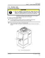
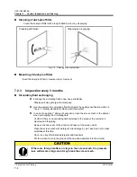
Страница 157: ...ust proof filters are installed on the front and left side of the product There are totally four filters and all they have the same shapes 2 They can be removed as shown in the drawing below Care shou...

Страница 158: ...on written in Table 7 1 Quality standard for clean water tap water z In case of using the Y strainer of accesarry clean the screen mesh in the strainer when exchanging the circulating fluid Confirm if...

Страница 159: ...e If it is necessary to shorten the circulating fluid temperature rising time set this function in advance For details refer to 5 17 Warming up function Anti snow coverage function To prevent the snow...

Страница 160: ...ethod of drain the circulating fluid from the product 3 After draining cover the product with a sheet and store Prepare the sheet 7 4 1 Discharge of the circulating fluid and facility water 1 Shut off...

Страница 161: ...25 34 Electric system Rated power consumption 8 kW kVA 5 8 6 8 4 8 7 10 4 11 6 Sound level Front 1m Height 1m dB A 62 66 Water proof specification IPX4 Accessory Alarm cord list label 2pc English 1pc...

Страница 162: ...rent 7 A 16 Electric system Rated power consumption 7 kW kVA 10 1 11 1 Sound level Front 1m Height 1m dB A 66 Water proof specification IPX4 Accessory Alarm cord list label 2pc English 1pc Japanese 1p...

Страница 163: ...M Q026 B Chapter 8 Documents HRSH Series 8 1 Specifications 8 3 8 1 3 Communication specification Regarding the communication specification refer to the operation manual communication function HRX OM...

Страница 164: ...50 A 20 HRSH200 A 20 Fig 8 1 Outline dimensions Dimensions for the positions of the anchor bolts View a a 48mm 1 9in 1020mm 40 2in 670mm 26 4in 138mm 5 4in 8x 12mm 0 5in 617mm 24 3in 954mm 37 6in 984m...

Страница 165: ...ne dimensions Dimensions for the positions of the anchor bolts View a a 850mm 33 5in 1035mm 40 7in 1720mm 67 7in a a In case of HRSH A 40 752mm 29 6in 50mm 2in 756mm 29 8in 670mm 26 4in 1100mm 43 3in...

Страница 166: ...Ref high press Heat exchanger Temp sensor Ref suction Press sensor Ref low press FAN Level switch Ball tap Press sensor Outlet Temp sensor Outlet Temp sensor Return Fluid level gauge Over flow port A...

Страница 167: ...8 5 Cooling capacity HRSH200 A 20 0 5 10 15 20 25 5 10 15 20 25 30 35 Circulating fluid temperature Cooling capacity kW 0 5 10 15 20 25 30 5 10 15 20 25 30 35 Circulating fluid temperature Cooling ca...

Страница 168: ...SH250 A 20 40 8 5 Pump capacity 8 5 1 HRSH150 200 A 20 Fig 8 7 Pump capacity HRSH150 200 A 20 0 0 1 0 2 0 3 0 4 0 5 0 6 0 10 20 30 40 50 60 70 80 90 100 110 120 130 Circulating fluid flow L min Pressu...

Страница 169: ...50 A 20 40 0 0 1 0 2 0 3 0 4 0 5 0 6 0 7 0 8 0 9 0 20 40 60 80 100 120 140 160 180 Circulating fluid flow L min Pressure MPa 0 10 20 30 40 50 60 70 80 90 Lifting head m Fig 8 8 Pump capacity HRSH250 A...

Страница 170: ...the product The fan can start and stop intermittently and without warning z DO NOT operate the product without cover panels fitted This symbol stands for a possible risk of hot surface and burns The...

Страница 171: ...HRSH Series 8 6 Types of hazard labels For HRSH A 40 8 11 8 6 1 Locations of Hazard Labels There are various warning labels on the product to show the potential hazards Fig 8 9 Warning label position...

Страница 172: ...8 Documents 8 7 Compliance standard HRSH Series 8 12 8 7 Compliance standard This system conforms to the following standards Table 8 3 Compliance standard EMC Directive 2004 108 EC CE Marking Machiner...

Страница 173: ...l Bussy Saint Georges F 77600 Germany SMC Pneumatik GmbH 49 6103 402 0 Boschring 13 15 D 63329 Egelsbach Greece SMC Hellas E P E 30 210 2717265 Anagenniseos 7 9 P C 14342 Nea Philadelphia Athens Hunga...

Страница 174: ...eck and record the condition at start right after setting up Thermo chiller Daily Check Sheet Operation conditions Presence of error Present Not present Circulating fluid temp Fluid amount Inside Outs...

Страница 175: ...as a secondary failure of the product caused by the failure of equipment connected to the product 6 The failure was caused by a natural disaster such as an earthquake typhoon or flood or by an acciden...

Страница 176: ...rm checks and maintenance daily checks and regular checks specified in the Operation Manual and Maintenance Manual Record the check and maintenance results on the daily check sheet attached to the Ope...

Страница 177: ......

Страница 178: ...101 0021 JAPAN Tel 81 3 5207 8249 Fax 81 3 5298 5362 URL http www smcworld com Note Specifications are subject to change without prior notice and any obligation on the part of the manufacturer 2011 SM...

Отзывы: