Circulating Fluid Temperature Controller
Thermo-chiller
Dual Channel Refrigerated Thermo-chiller for Lasers
HRL
Series
Contact Input/Output
Communication Functions
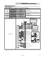
Contact Input/Output, Analog Output Communication Specifications
Item
Specifications
Contact
input signal
1, 2, 3
Insulation method
Photocoupler
·
Run/Stop signal
·
External switch signal
·
Operation mode request signal (Contact input 3 fixed)
Rated input voltage
24 VDC
Operating voltage range
21.6 to 26.4 VDC
Rated input current
5 mA TYP
Input impedance
4.7 k
Ω
Contact
output signal
1, 2, 3, 4, 5, 6
Rated load voltage
48 VAC or less/30 VDC or less
·
Run status signal
·
Alarm signal
·
TEMP READY signal, etc.
Maximum load current
800 mA AC/DC or less
∗
1
Minimum load current
5 VDC 10 mA
Analog
output signal
1, 2
Output voltage range
0 to +10 V
—
Maximum output current
10 mA
Output accuracy
±
0.4% F.S. or less
Output voltage
24 VDC
±
10% 200 mA MAX
∗
1
(No inductive load)
Circuit diagram
∗
1 Make sure that
the
total load current is 800 mA or less. When using
the
power supply of this product, make sure that
the
total load current is 200 mA or
less.
User’s system side
To the thermo-chiller
24 VDC
+
–
+
–
–15 V
100
Ω
ANALOG COM
24 COM
1
24 COM
+24 VDC (Output)
4.7 k
Ω
4.7 k
Ω
4.7 k
Ω
+15 V
–15 V
100
Ω
+15 V
ANALOG COM
I
n
te
rn
al
c
i
rc
ui
t
14
3
16
4
6
19
7
20
8
15
5
18
11
23
10
22
Contact output 4: OFF
Contact output 5: OFF
Analog output 1: CH2 circulating fluid temperature
Run/Stop
Operation mode request (Momentary)
Contact output 3: “WRN”
[Warning alarm occurrence OFF]
Contact output 2: “FLT”
[Fault alarm occurrence OFF]
Contact output 1: Operation status
[Operation ON]
Contact output 6: OFF
2
24 VDC
+24 VDC (Input)
EXT 24 VDC
EXT 24 COM
Power
supply
Analog output 2: CH2 electric conductivity
External switch
24 COM (Output)
Contact output 1-5 common
Contact output 6 common
Analog output 1 common
Analog output 2 common
24 VDC
1
14
2
1
14
3
2
Power
supply
24 VDC
2
4 COM
4
4
3
Wh
en using th
i
s produ
ct
’s
p
ower supply,
c
onne
c
t p
i
n
1
to pin
2
and
the
COM
sid
e
of each conta
c
t
i
nput
signal to pin 14.
Wh
en using a us
e
r’ s
p
ower supply,
c
onn
ect
the
24
VDC + sid
e
t
o
p
in
2
and
the
C
O
M sid
e
of
e
ac
h
c
on
t
a
ct
i
n
p
ut s
i
gnal
t
o t
he
us
e
r’s
p
ow
e
r C
O
M
.
Power supply usage example
This product’s power supply
usage example
User’s power supply
usage example
16


