•
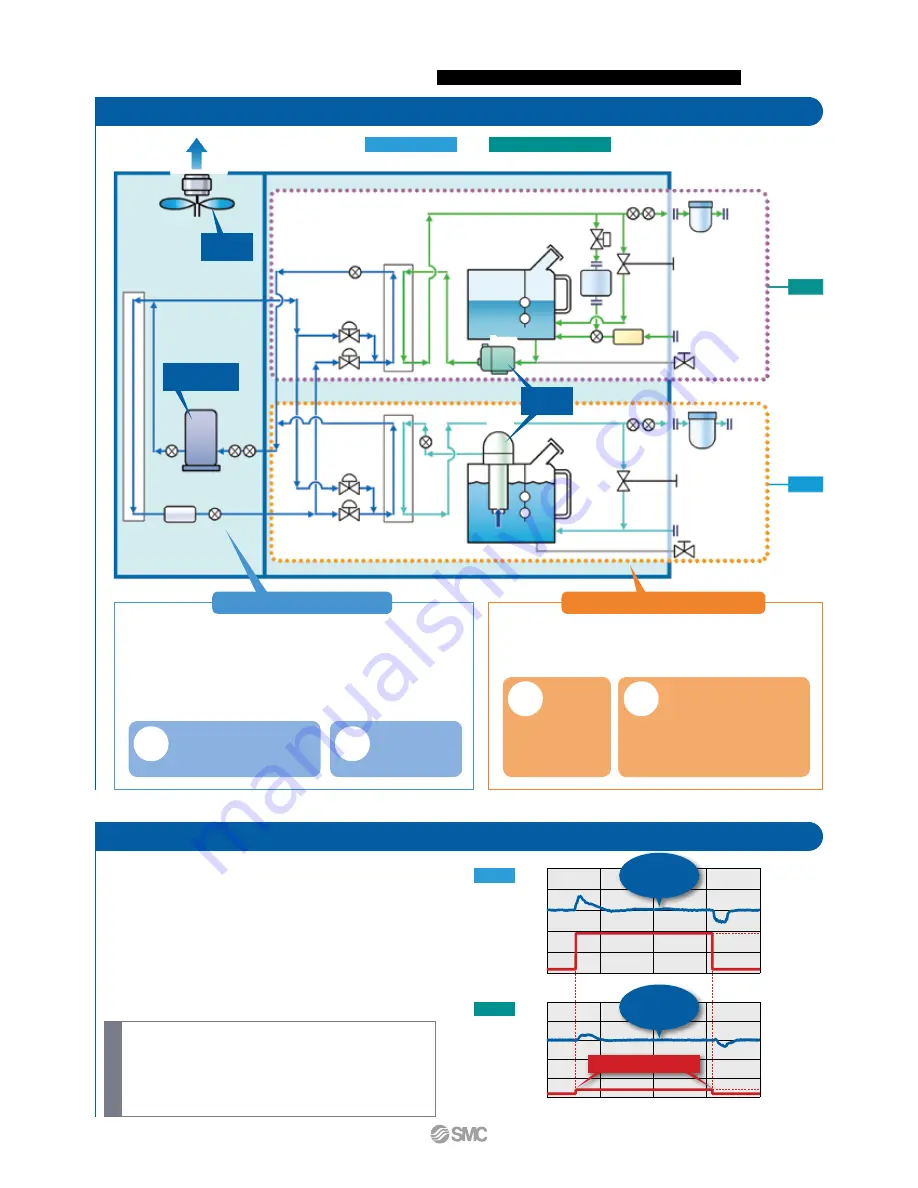
The inverter compressor compresses the refrigerant gas and discharges high-
temperature, high-pressure refrigerant gas.
•
In the case of air-cooled refrigeration, the high-temperature, high-pressure refrigerant gas is
cooled down by inverter fan ventilation in the air-cooled condenser, where it is then liquefied.
•
The liquefied high-pressure refrigerant gas expands and its temperature lowers when it
passes through expansion valve A, where it vaporizes after receiving heat from the
circulating fluid in the evaporator.
•
The vaporized refrigerant gas is sucked into the inverter compressor and compressed again.
•
When heating the circulating fluid, the high-pressure, high-temperature refrigerant gas
is bypassed into the evaporator by expansion valve B to heat the circulating fluid.
•
After the circulating fluid discharged from the inverter pump is heated or cooled by
the user’s equipment, it returns to the tank.
•
The circulating fluid is sent to the evaporator by the inverter pump, and is
controlled to a set temperature by the refrigeration circuit, to be discharged to the
user’s equipment side again by the thermo-chiller.
Refrigeration circuit
Circulating fluid circuit
The combination of inverter control of the
compressor and fan, and the precise
control of expansion valves A and B
realizes energy saving operation without
waste and high temperature stability.
Adjusting the
discharge
pressure by
pump inverter
control eliminates
wasteful discharge of
the circulating fluid and
realizes energy saving
operation.
Since the refrigeration circuit is controlled
by the signals from 2 temperature sensors
(for return and discharge), precise
temperature control of the circulating fluid
can be achieved. Therefore, there is no need for a
tank with a large capacity to absorb the circulating
fluid temperature difference, as high temperature
stability can be achieved even with a small-size tank.
This also contributes to space saving.
One compressor controls
2 channels which realize
the independent
temperature control of 2
systems.
Ventilation
Inverter
fan
Inverter
compressor
Inverter
pump
Temperature
sensor
Temperature
sensor
Temperature
sensor
Pump
Expansion valve B
Expansion valve B
Expansion valve A
Expansion valve A
Pump
CH2
CH1
(Optical
system)
(Oscillator)
Temperature of
CH1: Oscillator
and
CH2: Optical system
is controlled individually.
One compressor controls 2 channels.
POINT
POINT
POINT
POINT
By controlling the inverter compressor, inverter
fan, and electronic expansion valve simultaneous-
ly, it maintains the good temperature stability when
the heat load fluctuates.
•
Outdoor air temperature: 32°C
•
Circulating fluid temperature setting: 20°C/25°C (CH1/CH2)
•
Heat load in the user’s equipment: 26 kW/1 kW (CH1/CH2)
•
Power supply: 200 V 60 Hz
•
Circulating fluid flow rate: 125 LPM/10 LPM (CH1/CH2)
•
External piping: Bypass Heat load
∗
For HRL300-A-20
Temperature stability:
±
0.1
°
C (CH1)
When a load is stable
Pressure sensor
Pressure sensor
Pressure
sensor
Pressure
sensor
Circulating
fluid outlet
Circulating
fluid outlet
Particle filter
Particle filter
Fan
Air-cooled condenser
Compressor
Refrigerant filter
Heat
exchanger
Heat
exchanger
Level
switch
Level
switch
Drain port
Drain port
DI sensor
Circulating fluid
return port
Circulating fluid
return port
Flow
meter
DI filter
Solenoid
valve
Bypass
valve
Bypass
valve
Temperature
sensor
Temperature
sensor
Temperature sensor
Circulating fluid tempe
rature [
°
C]
Circulating fluid tempe
rature [
°
C]
Heat load fluctuation
When a load
is stable
±
0.1
°
C
When a load
is stable
±
0.5
°
C
26 kW load
0 kW load
17
18
19
20
21
22
0
10
20
30
40
1 kW load
0 kW load
22
23
24
25
26
27
0
10
20
30
40
Time [Minute]
CH1
CH2
Conditions
2
Circulating Fluid Temperature Controller
Thermo-chiller
Dual Channel Refrigerated Thermo-chiller for Lasers
HRL
Series


