


16
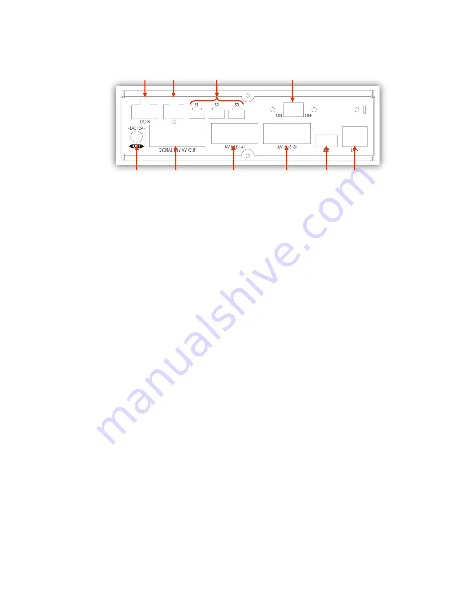
3-2. Rear
①
Power Connector
Use the included power cable bundle for this connection, the battery cable
connects to the battery power and the ACC cable connects to the ignition or
main power switch.
②
Car Signal Connector
Use the car signal cable bundle for this connection. Connect the appropriate
car signals to the labeled cables.
③
Serial Ports
Port 1: Connect external device usually used for system maintenance
Port 2: Connect external device usually used to connect EMS Alert Unit
Port 3: Connect external device usually allotted for external GPS
④
Main Power Switch
⑤
Power out (DC 12V)
⑥
Digital IO / AV out Connector
Digital Input 1: Allotted for RPM signal
Digital Input 2 ~ 8: Connects to other signal inputs such as panic switch,
horn, door open and close, etc.
Digital Output 1 ~ 2
Audio / Video Out
⑦
AV In (1~4) Connector
Cameras 1 ~ 4: Video, audio, and 12 V power supply
⑧
AV In (5~8) Connector
Cameras 5 ~ 8: Video, audio, and 12 V power supply
⑨
USB connector
Supports firmware up-grade, set up file upload / download, and network
connection
⑩
Ethernet connector
Supports network connection
⑤
⑥
⑦
⑧
⑨
⑩
ㅇ
①
②
③
④
Содержание SVC400GPS-L
Страница 43: ...43 3 1 1 PC Viewer Control Buttons ...
Страница 44: ...44 3 1 2 Control Buttons and Indicators ...
Страница 57: ...57 Blurred Image ...
Страница 86: ...86 Appendix C Recording Time Table ...
Страница 87: ...87 ...
Страница 88: ...88 ...


