H12AE52004
4 LEDs
1 M
DC 12V
View 360°
360°
720P
LENS
30/25 FPS
720P
DVR
4CH
optional
Extending
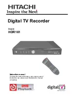
Vehicle Camera Appearance
Vehicle Camera Installation Diagram
1
2
3
5
6
4
1. Lens 1 (Front)
2. Lens 2 (Right)
3. Lens 3 (Inner)
4. Lens 4 (Left)
5. Cable collect slot
6. 3M Double-side tape
1. Install camera on windshield by
adhesive bracket
2. Pick up a best location for
installation.
4. To connect power
cable to Mini USB hole.
3. To adjust a best view angle.
5. To connect the other end
with the “Video In” slot in DVR.
Light Signal
4 CH DVR / All in one Camera
Vehicle Surveillance Camcorder
Standard Set
(1) Device
(2) Camera
(3) Power cord (black/blue/red)
(4) Alarm cable
(5) IR extension cord
(6) Remote controller
Optional Accessories
(1) USB interface SD card reader.
(2) 4/8/16/32G Class10 above SD card。
(7) Microphone
(8) Velcro strap
(9) Double-side3M tape
(10) Bracket mount
(11) CD
(12) Quick start guide
(3) GPS Module
(4) USB WIFI
(5) External connect Vehicle Camera
Accessories
▪
Installation Precautions
1. Make sure power connections clear enough to you before installation.
2. System installation is required professional installers and ventilation space.
3. Please use recommended and genuine storage device.
4. Please contact local dealers in case of service requirement.
▪
In Use Precautions
1. Please keep the inner components off any solid or liquid.
2. Please do not disassemble the equipment for warranty issue. Please contact local
dealers or the manufacturer for prompt service.
3. Please remove the battery if remote control keeps idle for quite a long while.
4. The equipment best connects with ground wire in case of outdoor cameras connection
or alarm I/O connection. This is to keep the DVR away from static electricity damage.
▪
Surrounding
1. Please have the DVR under recommended temperature away from the sun and
heating source.
2. Please keep this equipment away from humid surrounding.
3. Please keep this equipment away from smoke and dust.
4. Please do not drop the equipment.
5. Please keep this equipment in ventilation space.
6. Please supply rated voltage and Amp. To the equipment.
7. Please keep flammable objects away from the equipment.
Safety Precautions
Mobile DVR Dimension
7
10
8
9
11
12
13
14
1
2
3
4
5
6
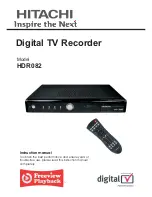
(1). Power Light (2). Recording Light (3). Wifi Light
(4). GPS Light (5). IR receiver (6). SD Card Slot
(7). GPS Connector: For connect with G-Mouse to use GPS function.
The GPS function includes record vehicle location, speed, longitude and latitude.
(8). EXT: Video output jack, connect with parking assist camera
(9). MIC: Microphone jack, connect and record audio with microphone.
(10). Composite cables :including video output, audio output and USB connector.
(11). Alarm Input: Alarm input connector, use by parking assist camera.
(12). Camera Connector: Connect with dedicated vehicle camera, which able to record
360°surrounding view.
(13). IR Extension Cable Connector: Once upon connecting with the extension cable,
the IR receiver will only receive signal from extension cable, cannot control by
remote controller.
(14). Power Connector: To cooperate with power management function
(in OSD), it can provide delay shut down function.
Power Cable (Black/Blue/Red)
1. Positive Port (Red cable): DC8~32V power input.
2. ACC Control (Blue cable): Can setup delay shut
down recording after turn off engine.
3. Negative Port(Black cable): GND
Alarm Cable(Black/Yellow)
1. Positive 12V ALARM Input (Yellow cable): Connect
with Positive port on parking assist camera.
2. Negative GND(Black cable): GND
●
Power Light (GREEN)
No light = No power supply.
Light on = Stable power supply.
●
Recording Light (RED)
No light = No recording.
Light Blinked = Recording.
Light Blinked Fast = Force recording.
●
WiFi Light(Orange)(optional)
No light = Not connecting with WiFi
Light Blinked = WiFi connecting
(NOTE: The device cannot recording during video playback on itself .)
●
GPS Light (BLUE)(optional)
No light = Not position yet.
Light Blinked = Position successfully
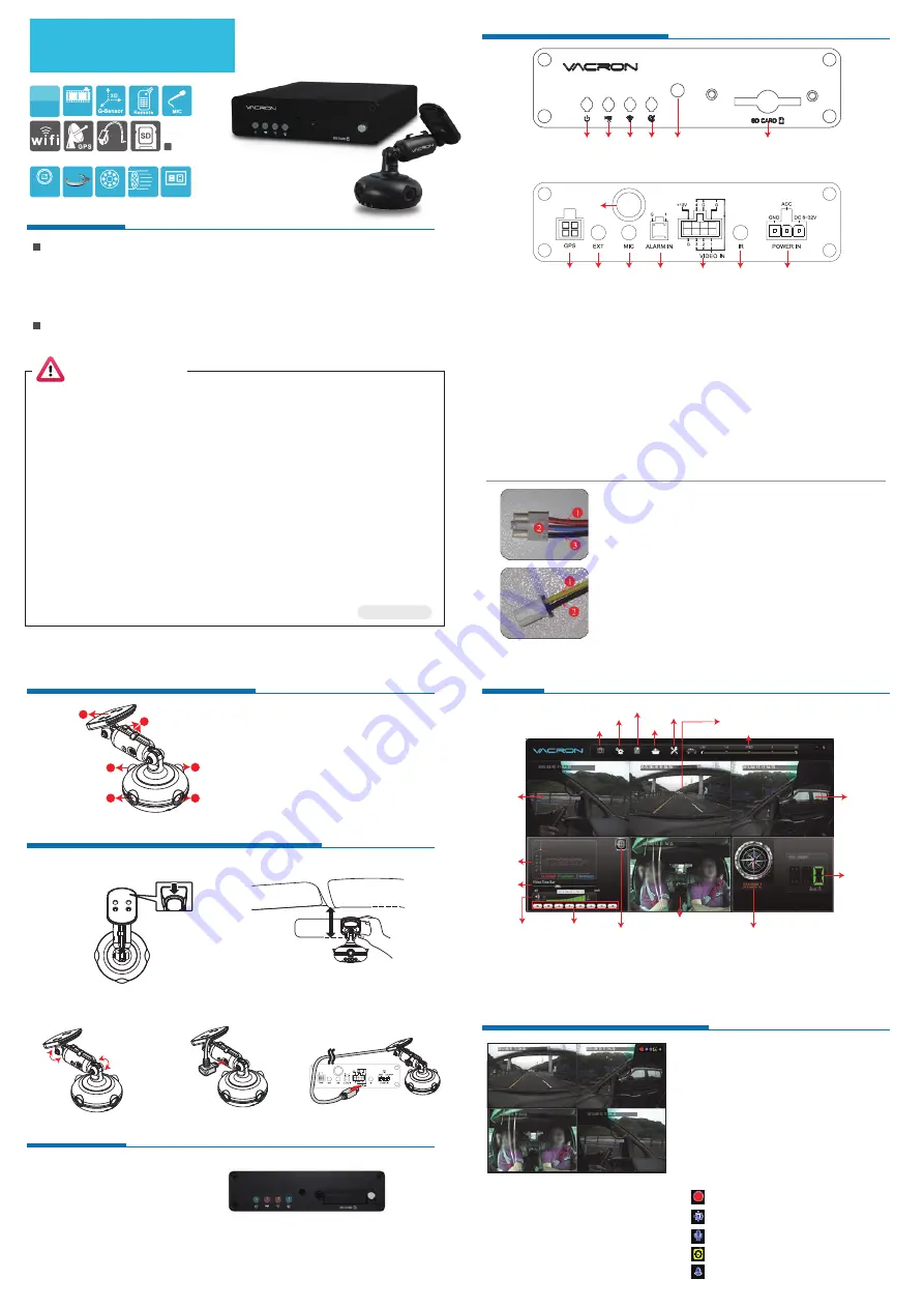
Viewer
Real Time Monitoring Mode
(1) Monitor Screen Operation Instruction:
• For display 1~4 channel separately, use
remote controller switch channel.
• To show quad display, press the quad
display button.
• To open menu, press Menu button.
• To playback, press Playback button.
(2) Icon Description:
• : Recording
• : GPS sensor position successfully.
• : Microphone ON
• : Activate event recording
• : Alarm
1
2
3
4
0 km/h
「
Direction and Latitude
」、「
Speed
」、「
Google Map
」
by GPS function, GPS is optional.
CH3(Vehicle inside
CH1(Front view)
CH2
(Right view)
CH4
(Left view)
Direction and Latitude
Speed
Capture
Configuration
Backup
Playback
Format
Footage playback speed
MAP
G-Sensor
Footage
playback
speed
Volume
Control panel
VVH-MDE52 (Vehicle DVR)
AVM-1276 (Vehicle Cam)