HGM6100K Series
Automatic Generator Module
OPERATING MANUAL
Smartgen Electronics
Страница 1: ...HGM6100K Series Automatic Generator Module OPERATING MANUAL Smartgen Electronics ...
Страница 2: ...roduct names used within this publication is owned by their respective companies Smartgen electronics reserves the right to change the contents of this document without prior notice Software Version Version Date Note 1 0 2009 10 10 Original release 1 1 2010 04 07 Add a typical wiring diagram and an AUX INPUT4 38 Pin and an AUX INPUT5 39 Pin and an Earth wire 40 Pin 1 2 2010 04 20 Add a language of...
Страница 3: ...ION 9 5 PROTECTION 9 5 1 WARNING 9 5 2 SHUTDOWN ALARM 10 6 CONNECTING TERMINAL 11 7 PARAMETER RANGE AND DEFINE 14 7 1 PARAMETERS TABLE TABLE 1 14 7 2 PROGRAMMABLE OUTPUT 1 4 TABLE TABLE 2 19 7 3 PROGRAMMABLE DIGIT INPUT 1 5 TABLE ALL IS VALID WHEN CONNECT GRAND B TABLE 3 21 7 4 SENSOR SELECTION TABLE 4 22 7 5 CONDITIONS OF CRANK SUCCEED TABLE 5 23 8 PARAMETER SETTING 24 9 SENSOR SELECTION 25 10 CO...
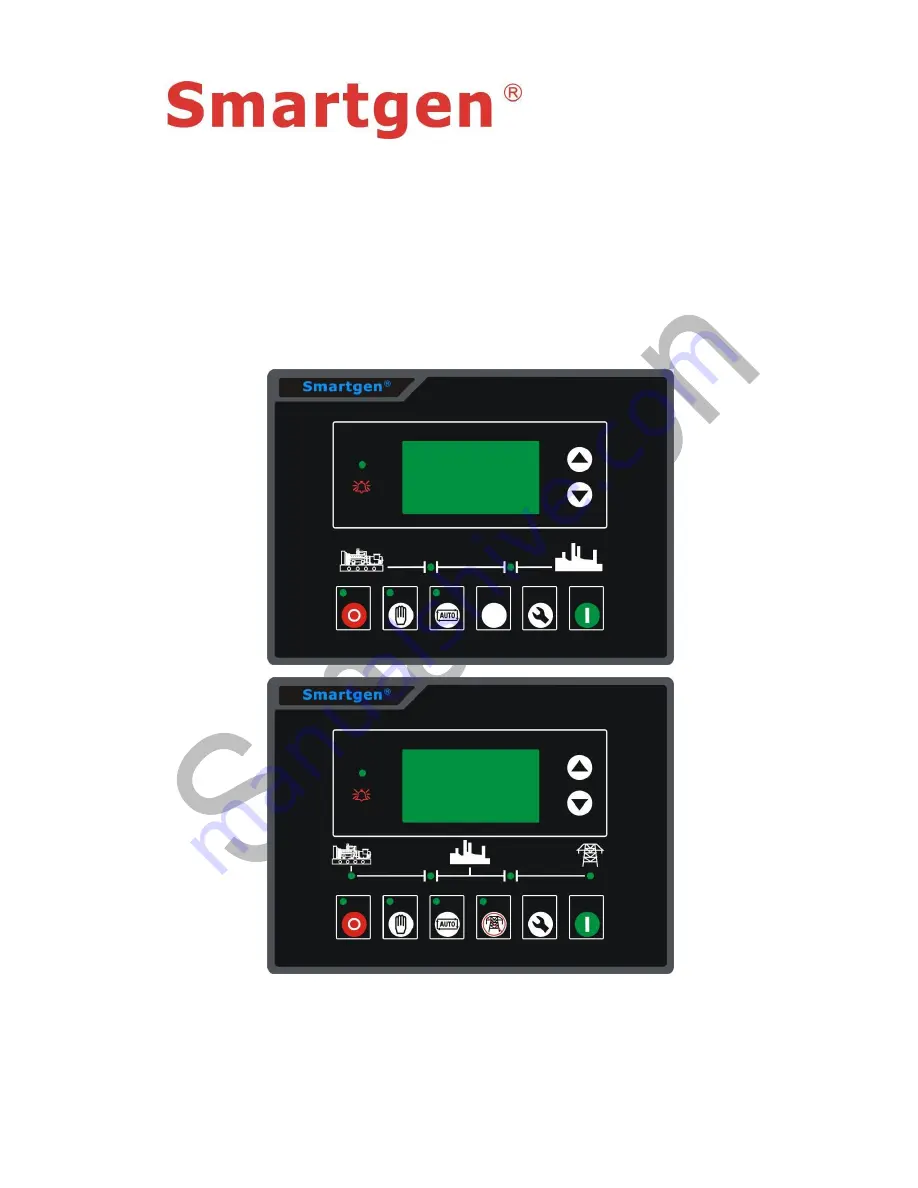
Страница 4: ... units automation system 2 PERFORMANCE AND CHARACTERISTICS HGM6100K controller has four types HGM6110K 6110KC Automatic Start Module it controls generator to start stop by remote start signal HGM6120K 6120KC Based on HGM6110K 6110KC and add mains AC monitoring Mains Generator automatic switching control functions AMF especially suitable for the automation system composed by Mains and Generator Not...
Страница 5: ...ansfer ATS control and completely faults display protection With ETS idle control pre heat control raises speed control functions and all types of them are belong to relay output Parameters setting Allow user to modify setting and store them by inside internal FLASH memory the parameters can not be lost even with power off All of parameters can be set not only from the front panel but by PC via SG...
Страница 6: ...t Relay Output 16 Amp DC28V at supply voltage Fuel Relay Output 16 Amp DC28V at supply voltage Auxiliary Relay Output 1 7 Amp DC28V Auxiliary Relay Output 2 7A 250VAC passive Auxiliary Relay Output 3 16A 250VAC passive Auxiliary Relay Output 4 16A 250VAC passive Overall Dimensions 209mm x 153mm x 55mm Panel cutoff 186mm x 141mm C T Secondary 5A rated Operating Temp Range Temperature 25 70 º C Humi...
Страница 7: ...hen gens are normal HGM6110KC without Set Confirm Enters into Set menu after pressing this and can shift cursor to confirm Page up increase Screen pages turning Shift cursor and increase its position no in setting Page down decrease Screen pages turning Shift cursor and decrease its position no in setting 4 2 AUTOMATIC OPERATION This mode is activated by pressing the LED indicator is illuminating ...
Страница 8: ...ormal If alternator s voltage frequency meets to requirement of load gens will close and relay is outputting then genset will enter into normal running with load and gens indicator is light if genset voltage and frequency is abnormal controller will alarm and stop engine gens alarming is displayed LCD Sequence of Auto Stop a HGM6120KC When Mains recovery during genset running enters into mains vol...
Страница 9: ...ter genset runs well in high speed no matter mains is normal or not loading switch must be transferred into gens side 2 HGM6110KC Auto starts mode is active when press and its indicator is illuminating Then press to start generator it can automatic detect start successfully and genset automatic accelerates to Hi speed running If there is Hi temperature low oil level and voltage abnormal during die...
Страница 10: ... it will be displayed in LCD 7 Battery High Voltage When controller detected the voltage of genset battery is higher than threshold controller will send warning alarm signal and it will be displayed in LCD 8 Low water level When controller detected the warning of low water level input is active controller will send warning alarm signal and it will be displayed in LCD 5 2 SHUTDOWN ALARM When contro...
Страница 11: ... LCD 10 Start failed alarm During the start attempt times if genset start failed it will send a stop alarm signal and it will be displayed in LCD 11 Over frequency alarm When controller detected genset frequency is over than set for alarming it will send a stop alarm signal and it will be displayed in LCD 12 Under frequency alarm When controller detected genset frequency is under than set for alar...
Страница 12: ...op input 2 5mm Plant Supply ve Also supplies fuel start outputs 4 Fuel relay output 1 5mm Plant Supply ve from pin 3 16 Amp rated 5 Start relay output 1 5mm Plant supply ve from pin 3 16 Amp rated Connect to starter starting coil 6 Auxiliary relay output 1 1 5mm Plant Supply ve from pin 2 7 Amp rated Reference table 2 7 Auxiliary relay output 2 1 5mm Closed output 7 Amp rated 8 Relay common point ...
Страница 13: ...ary of all monitoring CT s 27 Generator A voltage monitoring 1 0mm Connect to Generator A output Recommend 2A fuse 28 Generator B voltage monitoring 1 0mm Connect to Generator B output Recommend 2A fuse 29 Generator C voltage monitoring 1 0mm Connect to Generator C output Recommend 2A fuse 30 Generator Neutral input 1 0mm Connect to generator neutral terminal AC 31 Mains A voltage monitoring 1 0mm...
Страница 14: ...en mains voltage is under than the point mains under voltage are active When the point is zero mains under voltage are disabled 4 Mains over volt 30 360 V 276 When mains voltage is over than the point mains over voltage are active When the point is 360V mains over voltage are disabled 5 Transfer Switch interval 0 99 9 s 1 0 It s the delay from mains is opened to generator closing or from generator...
Страница 15: ...p idle time 0 3600 s 0 17 ETS solenoid hold 0 120 s 20 It s the delay for energizing to stop 18 Fail to stop delay 0 120 s 0 19 ATS close time 0 10 s 5 0 Mains or Generator switch closing pulse width when it is zero output is continuous 20 Flywheel teeth 10 300 118 21 Gens abnormal delay 0 20 0 s 10 0 22 Gens over volt 30 360 V 264 When generator voltage is over than the point generator over volta...
Страница 16: ...or freq is over than the point and hold great than 2 seconds generator over frequency is active 28 High temperature 80 140 C 98 When engine temperature sensor value is over than this point and remain for 2 seconds send out shutdown alarm When the value is 140 send out warning alarm It s suited for engine temperature sensor only 29 Low oil pressure 0 400 kPa 103 When engine oil pressure sensor valu...
Страница 17: ...ds battery over voltage signal is active It s a warning alarm 34 Battery under volt 4 30 V 8 0 When generator battery voltage is under than the point and hold for 20 seconds battery under voltage signal is active It s a warning alarm 35 CT rate 5 6000 5 500 Current transformer rate 36 Full load current 5 6000 A 500 Mains or generator set maximum rated current 37 Over current percentage 50 130 120 ...
Страница 18: ...8 Aux input2 0 15 2 Low Oil Pressure input 49 Aux input2 valid 0 1 0 Factory default is closed 50 Aux input2 delay 0 20 0 s 2 0 51 Aux input3 0 15 10 Remote start input 52 Aux input3 valid 0 1 0 Factory default is closed 53 Aux input3 delay 0 20 0 s 2 0 54 Aux input4 0 15 11 Low fuel level warn 55 Aux input4 valid 0 1 0 Factory default is closed 56 Aux input4 delay 0 20 0 s 2 0 57 Aux input5 0 15 ...
Страница 19: ... 72 Select liquid level sensor 0 5 03 SGD Note 1 if set as higher temperature to prohibit stop or set programmable port as higher temperature prohibits stop and this port is active when temperature value is higher than set of higher temperature value or higher temperature alarm input is active controller send warning signal of higher temperature only and not stop Note 2 if set as lower oil pressur...
Страница 20: ...enerator breaker on 6 Closed Mains Switch mains breaker on HGM6120KC 7 Open ATS Switch breaker off The output delay is 3 seconds 8 Raise speed In the process of warm up when he entered the suction suck time for high speed warm up delay time Raise speed auxiliary input effective disconnect 9 Drop speed Enter into stop idling process or to ETS solenoid stop when alarm stop sucked and suck time to st...
Страница 21: ...ng engine running if the engine occur high temperature shutdown when the input is active the engine will first initiate cooling delay and then stop else will stop immediately 6 Gens closed state input The input state of generator closed 7 Mains closed state input The input state of Mains closed 8 Higher temp stop prohibit When it is active prohibit stop when higher temperature Details see Note1 9 ...
Страница 22: ...nerator to run If the Auto start Inhibit signals become active once more it will be ignored until the module has returned the mains supply on load and shutdown 7 4 SENSOR SELECTION TABLE 4 Num Content Description 1 Temperature Sensor 0 Not used 1 Defined Res Type 2 VDO 3 SGH Huanghe sensor 4SGD DongKang sensor 5 CURTIS 6 DATCON 7 VOLVO EC 8 SGX 9 Reserved Defined input resistance range is 0 6000Ω ...
Страница 23: ...pose is to make the starter and the engine to disconnect as soon as possible 2 Magnetic pickup sensor is installed in the engine block number of magnetic device testing flywheel 3 When choosing magnetic pickup sensor ensure engine flywheel teeth setting otherwise may appear over speeding shutdown or loss speed shutdown 4 If the generator is not magnetic pickup sensors please don t choose correspon...
Страница 24: ...ght alarm shutdown or other abnormal behavior c The over voltage threshold must be greater than the under voltage threshold otherwise both will occur at the same time over voltage and under voltage situation d The over speed threshold must be greater than under speed threshold otherwise you will receive both the over speed and under speed e As far as possible set the frequency crank disconnect to ...
Страница 25: ... type resistively curve for temperature sensor SGD curve 2 If use standard sensor with the curve can differ option item sensor curve input after adjusting adjustment can be determined according to save 3 When the input sensor curve X resistance must be in accordance with the order of big from small otherwise will enter errors 4 When the sensor is choosing nothing the sensor curves no affection LCD...
Страница 26: ...the positive supply Ve of the battery through the NC terminal and fuse of emergency stop button d The suitable operation should be taken to prevent the engine from crank success such as dismantling the connection of fuel check and assure that it is correct then connect with battery select manual mode the controller will execute program e Press down the starting button on the panel of controller th...
Страница 27: ...f it exist to mains on load after pass through the mains normal delay after cooling time and then shut down to go into standby state until the mains is abnormal again h After the mains is abnormal again the Generator will automatically crank into normal operation state and then close generator relay control the ATS to switch transfer to generator on load If the situation is not same as described a...
Страница 28: ...6100K Series Automatic Generator Module ISSUE 2011 04 12 Version 1 6 Page 28 of 31 HGM6120KC Typical wiring diagram Single phase 2 wires HGM6120KC 2 phase 3 wires HGM6120KC Note Recommend that the output of crank and Fuel expand high capacity relay ...
Страница 29: ...mal operation of the controller battery charger interference 2 Speed sensor input Speed sensor is installed in the engine block of magnetic device testing flywheel teeth it should be used with the controller of attachment 2 core shielding line shielding layer on the 16th pin controller the other end terminal the other two are respectively in signal controller and meet the terminals15th and 16th pi...
Страница 30: ...ssured into and damaged controller 13 FAULT FINDING Symptom Possible Remedy Generator inoperative Check the battery and wiring to the unit Check the DC supply Check the DC fuse Generator shutdown Check water cylinder temperature whether or not too high Check AC generator voltage Check the DC fuse Emergency shutdown If an Emergency shutdown switch is not fitted ensure that a positive is connected t...
Страница 31: ...ttery supply Check battery supply is present on the Fuel output of the module Check the speed sensing signal is present on the 6100K series inputs Refer to engine manual Unit operation but ATS Check ATS Check the connection between the ATS and the controller RS485 communication abnormal Check wiring Check COM ports set correctly Check the A and B RS485 line is reversed Check of RS485 conversion mo...