background image

SMA


Technologie AG

Introduction

User Manual

WB1100LV-11:FE2606

Page 7

2 Introduction

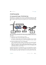
The Windy Boy inverters make it possible to operate small wind turbine systems
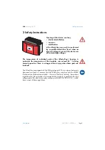
connected to the grid. Grid-connected means that the energy generated by the wind
energy system can be fed directly into an existing domestic grid, a stand-alone grid, or
the public grid.
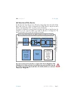
To this end, the Windy Boy converts the rectified DC voltage from permanent magnet
wind turbine generators, which varies with speed, into grid-compatible AC voltage.
Thus, the Windy Boy implies that mains grid voltage is always present!
The Windy Boy complies with all the VDEW (Verband der Elektrizitätswirtschaft –
German Electricity Industry Association) regulations for the parallel operation of power-
generating systems on the low-voltage grid of the electricity supply company. This also
encompasses the regulations of the German Professional Association for Precision
Engineering and Electrotechnology relating to the "automatic disconnection device for
power-generating systems" (SMA grid guard 2) and/or DIN VDE 0126. In addition to
this, the Windy Boy complies with the electromagnetic tolerance regulations and the
low-voltage regulations of the relevant combined European standards, as confirmed in
the CE declaration of conformity (10.3 "Declaration of Conformity (CE)" (Page 68)).
This part of the device's documentation primarily covers all topics relevant when
operating Windy Boy inverters. In addition to explanations of the operational methods
of the device and detailed technical data, advice as to data acquisition and analysis is
also provided.
Information relating to the installation and commissioning of the Windy Boy should be
taken from the installation manual delivered with the device. The Windy Boy inverter
has a special operating mode for wind turbines which allows performance adjustment
to the characteristic curve of the generator. In this way you can obtain maximum yields
from your wind energy system.
A wide input voltage range, very high efficiency and a freely configurable output
characteristic curve with the highest level of reliability are only some of the properties
that are useful for your grid-connected system, or a stand-alone system combined with
the Sunny Island.
The Windy Boy is compatible with all SMA communication products (RS232, RS485,
Powerline, radio, display), providing numerous possibilities for diagnostics, data
visualization and remote maintenance of your small wind energy system.

The Windy Boy may only be installed by trained specialists. The installer
must be approved by the local energy supplier. Carefully read this
installation manual. All prescribed safety regulations, the technical
connection requirements of the local energy supplier and all other
applicable regulations must be adhered to.

Содержание Windy Boy WB 1100LV

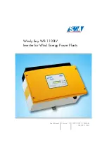
Страница 1: ...Windy Boy WB 1100LV Inverter for Wind Energy Power Plants User Manual Version 1 0 WB1100LV 11 FE2606 TBE WB1100LV...

Страница 2: ......

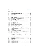
Страница 3: ...on 17 4 3 4 Description of the Operating Modes 17 4 4 Information on the Display 25 5 Setting the Display Language 29 6 Turbine Operation 31 6 1 Overview 31 6 2 Characteristic Curve Function 31 6 3 Ch...

Страница 4: ...tor Connection Data 51 9 2 Grid Connection Data 52 9 3 Device Description 53 10 General Information 55 10 1 Measurement Channels and Messages 55 10 1 1 Status Messages 56 10 1 2 Windy Boy Operating Pa...

Страница 5: ...the following explanation of the symbols used This symbol identifies an example This symbol indicates a notice where failure to follow the advice will make the procedure or operation more difficult Th...

Страница 6: ...Explanation of Symbols Used SMA Technologie AG Page 6 WB1100LV 11 FE2606 User Manual...

Страница 7: ...ration of Conformity CE Page 68 This part of the device s documentation primarily covers all topics relevant when operating Windy Boy inverters In addition to explanations of the operational methods o...

Страница 8: ...tovoltaic system and contact the SMA Hotline For stand alone systems which use Sunny Island Configure your Windy Boy according to the specifications in the Sunny Island manual Configuration of the Win...

Страница 9: ...housing in particular the temperature of the heatsink can exceed 60 C during normal operation There is a danger of burn injury when these parts are touched The Windy Boy is equipped with the SMA grid...

Страница 10: ...Safety Instructions SMA Technologie AG Page 10 WB1100LV 11 FE2606 User Manual...

Страница 11: ...by load shedding when the Windy Boy is disconnected from the grid e g in the event of grid faults or power outages The overvoltage protection system has the following tasks When a pre defined voltage...

Страница 12: ...y In the event of overvoltage immediately disconnect the Windy Boy s DC input The presence of excessive input voltage can lead to irreparable damage When the Windy Boy receives an excessive DC input v...

Страница 13: ...rated without any further modification or configuration The device parameters can however be modified if required An extra communication interface is required for ideal adaptation of the Windy Boy to...

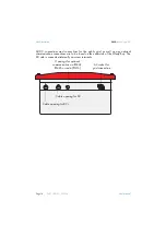
Страница 14: ...r the public grid as well as any optional communication connections are to be found on the underside of the Windy Boy The DC side is connected internally via screw terminals Openings for optional comm...

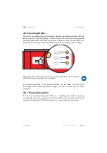
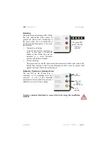
Страница 15: ...Boy has adequate DC voltage A complete description of the possible displays can be found in section 4 3 4 Description of the Operating Modes Page 17 These can be split into three categories 4 3 1 Norm...

Страница 16: ...is code is displayed 3 times in succession If the fault is still present the fault display starts again from the beginning The presence of excessive input voltage can lead to irreparable damage Immedi...

Страница 17: ...4 3 4 Description of the Operating Modes Page 17 to check the plausibility of the displayed normal operating modes Far more detailed diagnostics are possible using the communication options detailed i...

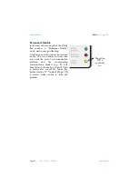
Страница 18: ...Stop The Windy Boy is in Stop mode Among other functions the measurement electronics are calibrated then the device switches to Waiting mode The Stop mode can also be manually set by the system operat...

Страница 19: ...sition with better ventilation Current derating The input current on the DC side exceeds the maximum possible input current The Windy Boy switches to the Current Derating mode in order to protect itse...

Страница 20: ...rid feeding A fault may exist that cannot be resolved on site You can attempt to correct the error with the aid of a communication interface and the corresponding communication product e g PC with Sun...

Страница 21: ...ault which can have the following causes Check if a general grid dropout has occurred check the operation of other electrical consumer devices and check if the fuse of the Windy Boy s feed in connecti...

Страница 22: ...y Boy has detected a fault relating to an unacceptable grid impedance If the Windy Boy frequently deactivates and displays this error during grid monitoring the cause can be an excessive grid impedanc...

Страница 23: ...ect the Windy Boy s DC input The presence of excessive input voltage can lead to irreparable damage Make sure that the input voltage never exceeds 60 V When the Windy Boy receives an excessive DC inpu...

Страница 24: ...efly on This code is displayed 3 times in succession If the fault is still present the fault display starts again from the beginning If the device fault leads to a major impairment of normal operation...

Страница 25: ...ver Tapping again switches the display to the next message After 2 minutes the illumination switches off automatically Display Messages in the Startup Phase The following messages are displayed during...

Страница 26: ...econds in the second line of the display If a measured value is responsible for the fault condition then the value measured at the time of the fault is displayed If another measurement is possible the...

Страница 27: ...re that the input voltage never exceeds 60 V When the Windy Boy receives an excessive DC input voltage it automatically disconnects from the grid and ceases its power feeding activity When the Windy B...

Страница 28: ...Unit Description SMA Technologie AG Page 28 WB1100LV 11 FE2606 User Manual...

Страница 29: ...t using the switches on the underside of the LCD assembly As the cover must be removed ask a qualified electrician to disconnect the DC and AC connections from the Windy Boy according to the installat...

Страница 30: ...Setting the Display Language SMA Technologie AG Page 30 WB1100LV 11 FE2606 User Manual...

Страница 31: ...ne is fed into the Windy Boy in the form of a rectified rotation speed variable DC voltage RPM and current intensity torque Most small wind turbine systems have a so called permanent magnet generator...

Страница 32: ...ects the mechanical components of your wind turbine system and thus contributes to a long service life for your system Additional adjustments are possible by means of optimizing the Windy Boy s maximu...

Страница 33: ...tation speed and the DC input voltage decrease The level of the voltage drop depends on the wind turbine used Characteristic Curve Operation As soon as the DC input voltage reaches the value defined i...

Страница 34: ...ding power into the grid for the period defined in T Stop If the DC input voltage increases once more the T Stop timer is deactivated and the Windy Boy resumes according to the defined curve operation...

Страница 35: ...ue to excessive power extraction and thus provides good startup properties The steeper curve section causes a strong increase in power extraction upon higher DC input voltages This behavior correspond...

Страница 36: ...ie AG Page 36 WB1100LV 11 FE2606 User Manual This shortens the period waited before activation please observe the regulations of the local energy supplier Only change the operating parameters if you k...

Страница 37: ...Windy Boy WB 1100LV PC or laptop with Windows 2000 Windows XP Home or Windows XP Professional with a free USB port PC software Sunny Data version 1 81 or higher available as a free download at www SM...

Страница 38: ...e cover by pulling it forward smoothly At the same time disconnect the PE connection from the cover Loosen the locking on the PE connection on the cover when you remove it Connect the USB service inte...

Страница 39: ...100LV 11 FE2606 Page 39 Check whether the Windy Boy s LEDs indicate correct operation In order to configure the Windy Boy a DC input voltage within the MPP range of the Windy Boy must be present The W...

Страница 40: ...Turbine Operation SMA Technologie AG Page 40 WB1100LV 11 FE2606 User Manual...

Страница 41: ...sible normal operation see section 4 3 4 Description of the Operating Modes Page 17 Naturally this information can also be obtained by using one of the communication options It is only necessary to cl...

Страница 42: ...Maintenance and Care SMA Technologie AG Page 42 WB1100LV 11 FE2606 User Manual...

Страница 43: ...k Sunny Beam using the USB service interface USBPBS see section 6 5 Changing the Power Curve with the Sunny Data PC Software and the USB Service Interface Page 37 With the Windy Boy the wind turbine s...

Страница 44: ...ction to a PC via the SWR COM or SWR COM USB is described in the documentation for the SWR COM SWR COM USB 8 1 2 Sunny Data Via RS232 Communication via cable one Windy Boy Requirements The Windy Boy m...

Страница 45: ...B interface converter connected to the USB port The installation of the RS485 Piggy Back is described in the Windy Boy s installation manual 8 2 Sunny Beam Simple system monitoring via radio for up to...

Страница 46: ...cable The installation of the Radio Piggy Backs and the connection to the PC is described in the Sunny Beam user manual 8 3 Sunny Boy Control Light The simple data logger for systems with up to 10 Wi...

Страница 47: ...ack RS485 communication via cable Requirements All Windy Boys must be equipped with an RS485 Piggy Back and the Sunny Boy Control must be equipped with an RS485 Piggy Back at the COM1 Sunny Boy interf...

Страница 48: ...ntrol Plus or Sunny Boy Control Light with a connection to a PC The connection between the PC and the Sunny Boy Control can be made via modem if required Large systems with more than 50 Windy Boys can...

Страница 49: ...a PC or via the Internet using the Sunny Portal 8 8 Sunny Portal The Sunny Portal is a high performance interface from SMA for the monitoring and presentation of your system in the Internet Details ca...

Страница 50: ...Extensions SMA Technologie AG Page 50 WB1100LV 11 FE2606 User Manual...

Страница 51: ...nom 25 V Max input current IDC max 62 A Max input power PDC 1240 W Recommended generator power at 5000 full load hours year Pturb max 800 W Recommended generator power at 2500 full load hours year Ptu...

Страница 52: ...rd 2 double implementation Power factor based on the current s fundamental frequency cos phi 1 Overvoltage category III Test voltage DC 1 6 kV 1 s routine testing 5 s type testing Test surge voltage 4...

Страница 53: ...voltage the higher the efficiency General Data Protection degree in accordance with DIN EN 60529 IP65 Dimensions w x h x d 434 mm x 295 mm x 214 mm approx Weight 29 kg approx External Interfaces Data...

Страница 54: ...Technical Data SMA Technologie AG Page 54 WB1100LV 11 FE2606 User Manual...

Страница 55: ...last reset Fac Grid frequency Error Identification of the present fault error Fehler Cnt The number of errors which have occurred since the last reset h On Total number of operational hours h Total T...

Страница 56: ...ating manual under the category Droop Mode MPP The Windy Boy is operating in MPP mode The Windy Boy takes the highest possible power output from the PV generator MPP is the standard display when opera...

Страница 57: ...ssary for the programmable wind curve and for adjusting a wind turbine system to the Windy Boy see also section 6 Turbine Operation Page 31 Name Explanation ACVtgRPro Voltage rise protection only rele...

Страница 58: ...parameter settings can be defined for countries for which no predefined setting exists Trimmed If country specific parameters have been changed trimmed is shown in the display dFac Max Maximum grid fr...

Страница 59: ...off via the Uac Max parameter intervenes Plimit Upper limit for AC output power Pmax Reduces the Windy Boy s maximum output power to adapt to wind turbines with lower output power P Wind Mid Defines t...

Страница 60: ...reshold after which the curve climbs more steeply UdcWindStart Defines the voltage at the moment when the Windy Boy begins to feed power into the mains grid and begins to extract power from the turbin...

Страница 61: ...Hz 0 2000 500 Betriebsart MPP UKonst Stop Turbine Mode Off Grid Turbine Default GER VDE 0126 1 1 SP RD1663 GB G83 Other trimmed GER VDE0126 1 1 dFac Max Hz s 0 1 4 0 0 25 dZac Max mohm 0 20000 750 E_T...

Страница 62: ...5 Upv Start V 20 60 25 Usoll Konst V 26 63 63 Parameters designated with are safety related grid monitoring parameters To change the SMA grid guard parameters you must enter your personal SMA grid gua...

Страница 63: ...0LV 11 FE2606 Page 63 10 1 6 Non Modifiable Parameters The following parameters are displayed in the parameter list but cannot be changed Name Unit Factory Setting Fac Pderating Fac Tavg ms 160 Plimit...

Страница 64: ...the grid operator whether the voltage at the feed in point can be adjusted or whether they agree to an alteration of the threshold value ACVtgRPro operating parameter ACVtgRPro for voltage quality mon...

Страница 65: ...Bfr Fac Srr The grid frequency is no longer within the permissible range Bfr or Srr is an internal message that has no meaning for the user The Windy Boy disconnects from the grid in order to avoid po...

Страница 66: ...W If the transformer reaches an unacceptably high temperature the Windy Boy stops feeding the grid until the transformer has returned to an acceptable temperature and grid feeding can resume The Trafo...

Страница 67: ...within the permissible range Bfr or Srr is an internal message which has no meaning for the user The Windy Boy disconnects from the grid in order to avoid potential damage or islanding The impedance i...

Страница 68: ...are compliant with the following standards EMC Emission DIN EN 61000 6 3 2002 08 DIN EN 61000 6 4 2002 08 DIN EN 55022 2003 09 class B Utility Interference DIN EN 61000 3 3 2002 05 DIN EN 61000 3 2 2...

Страница 69: ...ny Boy inverters see table Each Sunny Boy inverter can therefore be used as Windy Boy inverter and vice versa The respective operating mode of the inverter can be set or changed by the operator be mea...

Страница 70: ...ent tous les certificats relatifs aux appareils de la s rie d ondu leurs Sunny Boy sont transmissibles aux onduleurs correspondants Windy Boy Dichiarazione del produttore sulla trasferibilit delle cer...

Страница 71: ...nual WB1100LV 11 FE2606 Page 71 10 4 Clean report of findings The Windy Boy is equipped with the SMA grid guard 2 automatic disconnection device and is covered by the industrial trade association SMA...

Страница 72: ...General Information SMA Technologie AG Page 72 WB1100LV 11 FE2606 User Manual...

Страница 73: ...e systems based on the Sunny Island For this purpose the Windy Boy requires extra settings to ensure optimal operation and to deactivate the standard grid monitoring settings Refer to the Sunny Island...

Страница 74: ...Stand Alone Systems SMA Technologie AG Page 74 WB1100LV 11 FE2606 User Manual...

Страница 75: ...tline Have the following information available when you contact SMA Inverter type Type of wind turbine and AC DC converter Type of overvoltage protection Communication Serial number of the Windy Boy I...

Страница 76: ...ction conditions Altering the product or supplied software without authority The product malfunctions due to operating attached or neighboring devices beyond statutory limit values In case of unforese...

Страница 77: ......
Страница 78: ...A Technologie AG Hannoversche Strasse 1 5 34266 Niestetal Germany Tel 49 561 9522 4000 Fax 49 561 9522 4040 E Mail Info SMA de Freecall 800 SUNNYBOY Freecall 800 78669269 Innovation in Systems Technol...

Отзывы: