SB700U-11:SE3207
SMA America
4-19
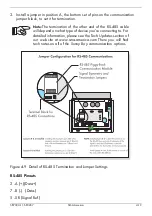
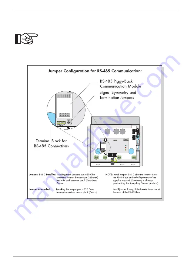
3. Install a jumper in position A, the bottom set of pins on the communication
jumper block, to set it for termination.
Note:
The termination of the other end of the RS-485 cable
will depend on what type of device you’re connecting to. For
detailed information, please see the Tech Updates section of
our web site at www.sma-america.com There you will find
tech notes on all of the Sunny Boy communication options.
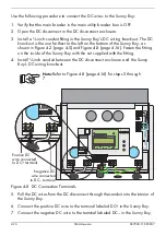
Figure 4-9 Detail of RS-485 Termination and Jumper Settings
RS-485 Pinouts
2 - A (+)(Data+)
7 - B (-) (Data-)
5 - SR (Signal Ref.)
Содержание Sunny Boy SB 700U
Страница 1: ...Sunny Boy SB 700U Installation Guide Version 1 1 SB700U 11 SE3207 TBE SB07U...
Страница 2: ...ii SMA America SB700U 11 SE3207...
Страница 14: ...1 6 SMA America SB700U 11 SE3207...
Страница 16: ...2 2 SMA AmericaSB700U 11 SE3207...
Страница 21: ...SB700U 11 SE3207 SMA America 3 5 Wall Mounting Bracket Figure 3 3 Dimensions of the wall mounting bracket...
Страница 24: ...3 8 SMA America SB700U 11 SE3207 11 Verify that the Sunny Boy 700U is firmly mounted in place...
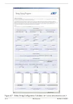
Страница 38: ...4 14 SMA America SB700U 11 SE3207 Figure 4 7 Online String Configuration Calculator at www sma america com...
Страница 46: ...4 22 SMA America SB700U 11 SE3207...
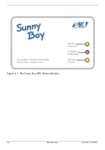
Страница 50: ...6 2 SMA America SB700U 11 SE3207 Figure 6 1 The Sunny Boy LED Status Indicator...
Страница 84: ...8 6 SMA America SB700U 11 SE3207...
Страница 85: ......

