background image


6-2

SMA America

SB700U-11:SE3207

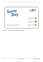
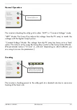
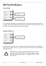
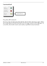
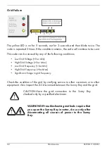
Figure 6-1  The Sunny Boy LED Status Indicator

Содержание Sunny Boy SB 700U

Страница 1: ...Sunny Boy SB 700U Installation Guide Version 1 1 SB700U 11 SE3207 TBE SB07U...

Страница 2: ...ii SMA America SB700U 11 SE3207...

Страница 3: ...t apply in all cases under some statutes and thus the above exclusion may not apply Specifications are subject to change without notice Every attempt has been made to make this document complete accur...

Страница 4: ...d operation of the Sunny Boy you must carefully read and follow all instructions cautions and warnings in this Installation Guide Safety and Hazard Symbols This symbol is used to call attention to imp...

Страница 5: ...or adhered to could result in dam age to or destruction of part or all of the SMA equipment and or other equipment connected to the SMA equipment Warnings and Cautions may also be accompanied by one o...

Страница 6: ...onnel PV arrays produce electrical energy when exposed to light and thus can create an electrical shock hazard Completely cover the surface of all PV arrays with opaque dark material before wiring the...

Страница 7: ...Recommended Clearances 3 4 Mounting Procedure 3 6 4 Wiring and Connecting the Sunny Boy Sequence of Connecting 4 2 Sunny Boy 700U Internal Components 4 3 Opening the Sunny Boy 700U 4 3 Locating Inter...

Страница 8: ...ction 6 15 Communication Options 6 16 Measuring Channels and Messages 6 18 Measuring Channels 6 18 Operating Mode 6 19 Sunny Boy 700U Operating Parameters 6 20 7 Troubleshooting General 7 1 Error mess...

Страница 9: ...otovoltaic PV inverter Note To help avoid problems during the installation fa miliarize yourself with the installation process by reading the entire Installation Guide before starting the installa tio...

Страница 10: ...ss power fed to the utility The power consumed by the local loads reduces the power needed from the utility Excess power may actually spin the utility meter backwards depending on the type of meter in...

Страница 11: ...d island condition PV Ground Fault Detection and Interruption The Sunny Boy is equipped with a ground fault detection device If a ground fault current greater than 1 Amp is detected the Sunny Boy will...

Страница 12: ...utility grid FCC Compliance The Sunny Boy has been tested and certified by a nationally recognized testing laboratory and conforms to all FCC Part 15 B EMI EMC emissions regulations Feature Overview...

Страница 13: ...y and or equipment damage and step by step instructions for mounting a Sunny Boy 700U inverter Section 4 Wiring and Connecting the Sunny Boy This section includes guidelines for selecting the correct...

Страница 14: ...1 6 SMA America SB700U 11 SE3207...

Страница 15: ...damage immediately to your SMA dealer and to the shipping company that delivered the Sunny Boy If it becomes necessary to return the Sunny Boy use the original packaging in which the Sunny Boy was de...

Страница 16: ...2 2 SMA AmericaSB700U 11 SE3207...

Страница 17: ...mounting a Sunny Boy 700U inverter WARNING To avoid injury lift the Sunny Boy careful ly and handle it carefully to prevent the weight of the inverter from causing you to lose your balance and fall If...

Страница 18: ...as no effect on performance but it can be objectionable if the inverter is mounted on a wall in a living area on the outside of a wall that is part of a living area or on certain types of materials su...

Страница 19: ...it is raining and if possible choose a day when the humidity is low to install it CAUTION If you are installing the Sunny Boy in a cabi net closet or other relatively small enclosed area you must pro...

Страница 20: ...unny Boy s heat sink In a nor mal operating environment with good ventilation eight inch es of clearance is adequate However if the airflow to the Sunny Boy is restricted or it is subjected to other a...

Страница 21: ...SB700U 11 SE3207 SMA America 3 5 Wall Mounting Bracket Figure 3 3 Dimensions of the wall mounting bracket...

Страница 22: ...mount the Sunny Boy 1 Locate the T shaped wall mounting bracket included in the shipping container with the Sunny Boy 2 Position the wall mounting bracket against the wall where you intend to mount t...

Страница 23: ...ed in the wall Tighten the screws until the bracket is held firmly against the wall see 1 in Figure 3 4 Do not overtighten the screws 6 Carefully lift the Sunny Boy into position near the mounting bra...

Страница 24: ...3 8 SMA America SB700U 11 SE3207 11 Verify that the Sunny Boy 700U is firmly mounted in place...

Страница 25: ...d the wires that carry the DC voltage from the PC array to the Sunny Boy in the order described in the procedures in this section Deviating from these pro cedures could expose you to lethal voltage th...

Страница 26: ...reakers ON 7 Turn the AC switches and or breakers ON To disconnect the Sunny Boy first turn OFF all AC disconnects and then all DC disconnects The AC system should always be disconnected before the DC...

Страница 27: ...connecting wires and cables to the Sunny Boy CAUTION Be careful not to misplace the screws or the lock washers as all four screws and lock washers are required to ensure that the cover is grounded pr...

Страница 28: ...are provided on the bottom of the Sunny Boy near each of the terminals for the wires to enter the case Figure 4 2 DC PE PE L N ENS1 ENS2 S15 S13 S11 S9 S7 S5 200V 150V 23 57 DC A S2 A B B S1 A S2 A B...

Страница 29: ...7 SMA America 4 5 Figure 4 2 Bottom View of the Sunny Boy 700U Showing 1 2 Wiring Knockouts CAUTION All knockouts in the Sunny Boy chassis are sized for 1 2 inch rigid conduit EMT DO NOT enlarge any o...

Страница 30: ...E wiring connections to the Sunny Boy 6 14 AWG 90 C 194 F solid or stranded copper wire WARNING The National Electrical Code NEC states that the inverter must be connected to a ded icated circuit and...

Страница 31: ...tage Drop Calculator tool for calculating the potential losses in AC wires is available on www sma ameri ca com The Sunny Boy 700U is designed to feed 106 V AC to 132 V AC to the utility grid at frequ...

Страница 32: ...fitting on the inside of the Sunny Boy with the nut supplied with the fitting 4 Install inch conduit between the main breaker box and the Sunny Boy s AC wiring knockout 5 Pull the AC wires through th...

Страница 33: ...nnection Terminals DC PE PE L N ENS1 ENS2 S15 S13 S11 S9 S7 S5 200V 150V 23 5 7 DC L N PE PE A S2 A B B S1 A S2 A B B S1 Equipment ground wire connected to PE terminal L1 AC Line wire connected to L t...

Страница 34: ...iagram of a PV System DC Connection Requirements All electrical installations DC and Protective Earth PE must be done in accordance with all local electrical codes and with the National Electrical Cod...

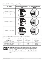
Страница 35: ...ion the range configuration plug and jumper to configure the Sunny Boy s DC input voltage range Table 4 1 page 4 11 lists the AC current and power specifications for the Sunny Boy 700U for each of the...

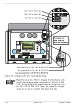
Страница 36: ...s set for 125 V DC to 250 V DC Store the jumper on a single empty pin in case it is needed later see Table 4 2 DC PE PE L N 23 5 7 DC S9 S7 S5 200V 150V A S2 A B B S1 A S2 A B B S1 ENS1 ENS2 S15 S13 S...

Страница 37: ...he Sunny Boy 700U DC Configuration Rated AC Current Maximum AC Current Maximum AC Power 125 V DC to 250 V DC 5 8 A 6 6 A 700 W 100 V DC to 200 V DC 5 0 A 5 7 A 600 W 75 V DC to 150 V DC 3 8 A 4 3 A 46...

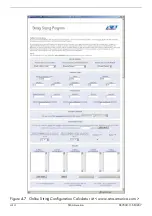
Страница 38: ...4 14 SMA America SB700U 11 SE3207 Figure 4 7 Online String Configuration Calculator at www sma america com...

Страница 39: ...e connecting any wires to the Sunny Boy or disconnecting any wires from the Sunny Boy Failure to do so could expose you to lethal voltages that can cause serious injury and or death CAUTION Verify the...

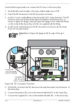
Страница 40: ...Sunny Boy with the nut supplied with the fitting 4 Install inch conduit between the DC disconnect enclosure and the Sunny Boy s DC wiring knockout Note Refer to Figure 4 8 page 4 16 for steps 5 throu...

Страница 41: ...Avoid using wire nuts to join any wires togeth er or to make any connections anywhere in the PV system Wire nuts are a frequent cause of unreliable connections resistive connections and ground faults...

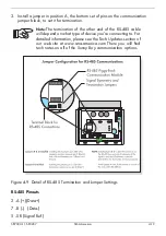
Страница 42: ...are met You can mix different Sunny Boy models on the RS 485 communica tion bus Requirements for RS 485 Communication The Sunny Boy 700U must be equipped with an RS 485 Piggy Back communication mod u...

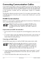
Страница 43: ...he other end of the RS 485 cable will depend on what type of device you re connecting to For detailed information please see the Tech Updates section of our web site at www sma america com There you w...

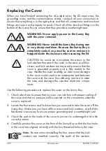
Страница 44: ...operly and is fully sealed to the case Handle the cover carefully as even minor damage to the cover could result in an inadequate seal between the cover and the case thus allowing moisture to enter th...

Страница 45: ...in the cover into the threaded holes in the case and turn them in until they are finger tight Be careful not to cross thread any of the screws 6 Verify that the cover is in the correct position and t...

Страница 46: ...4 22 SMA America SB700U 11 SE3207...

Страница 47: ...tes in a grounded configuration The array s negative conductor is connected to the grounding system inside the inverter as a part of the UL1741 Listed ground fault detection system The GFDI protection...

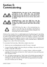
Страница 48: ...eshooting Note If there is adequate solar irradiation and the resulting PV input voltage is sufficient the Sunny Boy will automatically begin feeding power to the utility grid Note The Sunny Boy opera...

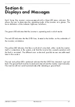
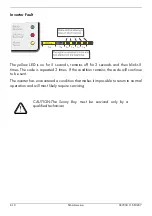
Страница 49: ...DI fuse located in the holder on the underside of the inverter is defective The yellow LED indicates that there is a fault of some kind either inside the inverter itself or somewhere in the system and...

Страница 50: ...6 2 SMA America SB700U 11 SE3207 Figure 6 1 The Sunny Boy LED Status Indicator...

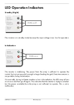
Страница 51: ...rray is sufficient to operate the control but not yet powerful enough to begin feeding the grid Data transmission is not possible during initialization Occasionally during inclimate weather or low sol...

Страница 52: ...onds and then the inverter resumes normal operation This status can also be adjusted manually operating mode Stop Waiting The inverter has determined that there is enough power from the array to opera...

Страница 53: ...ith the highest output power Constant Voltage Mode The voltage from the PV array has been set to a fixed value This value is set by using the Sunny Boy Control or the Sunny Data software The parameter...

Страница 54: ...ally The inverter will not restart automatically Defective GFDI Fuse The GFDI fuse located in the fuse holder on the bottom of the inverter is defective If the fuse has blown due to a ground fault the...

Страница 55: ...remains lit The Sunny Boy has detected a fault with the internal utility monitoring system When the inverter detects a fault of this kind it will no longer connect to the utility grid To correct this...

Страница 56: ...ltage Vac Max Low Grid Frequency fac Min High Grid Frequency fac Max Significant change in grid frequency Check the condition of the grid by varifying service to other customers or to other equipment...

Страница 57: ...The code is repeated 3 times If the condition remains the code will continue to be sent The inverter has detected an input voltage that is too high for safe operation WARNING Disconnect the PV array f...

Страница 58: ...then blinks 5 times The code is repeated 3 times If the condition remains the code will continue to be sent The inverter has encountered a condition that makes it impossible to return to normal opera...

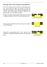
Страница 59: ...und Illumination The background illumination is activated by slightly knocking on the lid Knocking once more activates the next message on the display The background illumination is automatically deac...

Страница 60: ...5 seconds after all messages have been displayed the display starts from the beginning again First the E Today total energy produced on this day is displayed together with the current operating status...

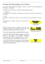
Страница 61: ...tion The bottom line indicates the type of a failure for 5 seconds Display of the value that caused the failure and the current value at 59 31Hz present 59 30Hz Failures that result from a specific va...

Страница 62: ...ltage A too high voltage on the input DC side is indicated with a blinking background illumination and the display shown on the side WARNING Disconnect the inverter from the supply voltage immediately...

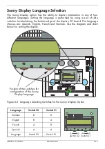
Страница 63: ...ocated along the bottom edge of the display PC board The language choices are Spanish English French and German Use the diagram and chart below for setting the display Position of the switches for con...

Страница 64: ...vironment Sunny Data Control This PC application is used to communicate with the Sunny Boy Control products It can be used to monitor multiple inverters download historical system data and adjust syst...

Страница 65: ...numerous additional sensors for the measurement of module temperature ambient temperature wind speed humidity and more Sunny Portal The Sunny Portal is a high performance interface from SMA for the m...

Страница 66: ...Fac grid frequency Pac power fed to grid Vpv PE PV voltage to earth for troubleshooting PV ground faults Temperature Temperature measured at IGBT module Ipv current from PV panels Max Temperature Max...

Страница 67: ...ing on conditions are not fulfilled yet Grid monitoring checking grid grid impedance MPP Search PV voltage is determined and set MPP Sunny Boy is in MPP mode V Const Sunny Boy is in constant voltage m...

Страница 68: ...Boy The amount of CO2 avoided is computed according to the kWh produced E total multiplied by the factor defined in the parameter CO2 Default USA UL1741 2005 OFF_GRID ADJUSTED USA UL1741 2005 Used for...

Страница 69: ...The time the inverters waits to connect to the grid after Vpv Start is exceeded This value defaults to 5 minutes after a utility fault T Stop s 1 1800 2 Time that the Sunny Boy wait until it disconne...

Страница 70: ...amount of CO2 avoided is computed according to the kWh produced E total multiplied by the factor defined in the parameter CO2 Default USA UL1741 2005 OFF_GRID ADJUSTED USA UL1741 2005 Used for adjust...

Страница 71: ...The time the inverters waits to connect to the grid after Vpv Start is exceeded This value defaults to 5 minutes after a utility fault T Stop s 1 1800 2 Time that the Sunny Boy wait until it disconnec...

Страница 72: ...e amount of CO2 avoided is computed according to the kWh produced E total multiplied by the factor defined in the parameter CO2 Default USA UL1741 2005 OFF_GRID ADJUSTED USA UL1741 2005 Used for adjus...

Страница 73: ...The time the inverters waits to connect to the grid after Vpv Start is exceeded This value defaults to 5 minutes after a utility fault T Stop s 1 1800 2 Time that the Sunny Boy wait until it disconnec...

Страница 74: ...ame Unit Range Default Description Plimit W 700 700 Upper limit of AC output power SMA SN Serial Number of the Sunny Boy Software BFR Firmware version of the operation control unit BFR Software SRR Fi...

Страница 75: ...and AC voltages at terminals inside the inverter Be sure to observe all of the safety precautions listed throughout this manual when doing so or hire a qualified professional If the system problem per...

Страница 76: ...urer and model of the module Output power of the module Open circuit voltage Voc of the module Number of modules in each string If it becomes necessary to send the Sunny Boy back to the manufacturer f...

Страница 77: ...equency is exceeding the allowable range Bfr or Srr is an internal message and is not important to the user The Sunny Boy assumes that the public grid is down and disconnects from the grid in order to...

Страница 78: ...or Srr is an internal message and is not important for the user Vac can also result from a disconnected grid or a disconnected AC cable The Sunny Boy assumes that the public grid is down and disconne...

Страница 79: ...d used in accordance with the instructions may cause harmful interference to radio communications However there is no guarantee that interference will not occur in a particular installation If this eq...

Страница 80: ...700U 11 SE3207 Sunny Boy Wiring Diagram Sunny Boy connection to 120 V AC utility grids SUNNY BOY 700U INVERTER BREAKER SIZE 1p 10 Amp The AC disconnect switch shown above may or may not be required by...

Страница 81: ...nge of Input Operating Voltage 125 250 V DC 100 200 V DC 77 150 V DC Maximum DC Power 780 W 670 W 510 W Maximum AC Continuous Output Power 700 W 600 W 460 W Current THD Less than 3 Output Power Factor...

Страница 82: ...current Protection 15 A Synchronization In Rush Current 3 6 A DC Voltage Ripple Less than 10 Power Consumption 0 1 W nighttime 4 W in operation Ambient Temperature Rating 13 F 113 C 25 C 45 C Enclosur...

Страница 83: ...mes s 120 50 88 110 120 57 6 62 4 103 2 108 0 129 6 134 4 141 6 146 4 N A max 0 1602 max 2 002 max 1 001 max 0 1602 SB700U 11 SE3207 SMA America 8 5 Trip Limits Trip Times Manufacturer s Accuracies Te...

Страница 84: ...8 6 SMA America SB700U 11 SE3207...

Страница 85: ......

Страница 86: ...Ib rica Tecnolog a Solar S L Barcelona Spain E mail info SMA Iberica com SMA Italia S r l Milan Italy E mail info SMA Italia com SMA France S A S Lyon France E mail info SMA France com SMA Technologie...

Отзывы: