SB700U-11:SE3207
SMA America
4-3
Sunny Boy 700U Internal Components
All of the terminals and connectors for DC input, AC output, and communications
are inside the Sunny Boy’s case. To gain access to these and other internal
components, you must remove the cover.
Opening the Sunny Boy 700U
Remove the four M5 screws and lock washers that attach the cover to the Sunny
Boy. Place the cover, screws, and lock washers aside where they will be out of your
way while you are connecting wires and cables to the Sunny Boy.
CAUTION:
Be careful
not to misplace the screws or the lock
washers, as all four screws and lock washers are required to
ensure that the cover is grounded properly and is fully sealed
to the case. Handle the cover carefully, as even minor dam-
age to the cover could result in an inadequate seal between
the cover and the case, thus allowing moisture to enter the
case and damage the sensitive electronic components.
Locating Internal Components
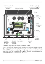
Figure 4-1shows the internal components of the Sunny Boy 700U. Refer to this
illustration whenever you need to locate a component to complete a step of the
installation procedure.
Содержание Sunny Boy SB 700U
Страница 1: ...Sunny Boy SB 700U Installation Guide Version 1 1 SB700U 11 SE3207 TBE SB07U...
Страница 2: ...ii SMA America SB700U 11 SE3207...
Страница 14: ...1 6 SMA America SB700U 11 SE3207...
Страница 16: ...2 2 SMA AmericaSB700U 11 SE3207...
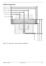
Страница 21: ...SB700U 11 SE3207 SMA America 3 5 Wall Mounting Bracket Figure 3 3 Dimensions of the wall mounting bracket...
Страница 24: ...3 8 SMA America SB700U 11 SE3207 11 Verify that the Sunny Boy 700U is firmly mounted in place...
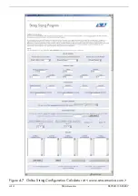
Страница 38: ...4 14 SMA America SB700U 11 SE3207 Figure 4 7 Online String Configuration Calculator at www sma america com...
Страница 46: ...4 22 SMA America SB700U 11 SE3207...
Страница 50: ...6 2 SMA America SB700U 11 SE3207 Figure 6 1 The Sunny Boy LED Status Indicator...
Страница 84: ...8 6 SMA America SB700U 11 SE3207...
Страница 85: ......

