4-10
SMA America
SB700U-11:SE3207
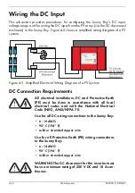
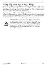
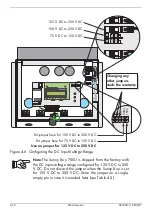
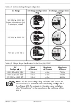
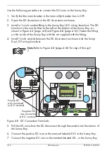
Wiring the DC Input
This subsection provides procedures for configuring the Sunny Boy’s DC input-
voltage range and for wiring the DC input from the PV array (via the DC disconnect
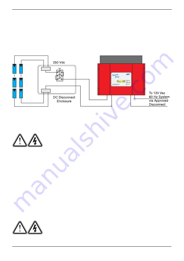
enclosure) to the Sunny Boy. Figure 4-5 shows a simplified wiring diagram of a PV
system.
Figure 4-5 Simplified Electrical Wiring Diagram of a PV System
DC Connection Requirements
All electrical installations DC and Protective Earth
(PE) must be done in accordance with all local
electrical codes and with the National Electrical
Code (NEC), ANSI/NFPA 70.
Use for all DC wiring connections to the Sunny Boy:
• 6 - 10 AWG
• 90° C (194° F)
• solid or stranded copper wire
Use for all Protective Earth (PE) wiring connections
to the Sunny Boy:
• 6 - 14 AWG
• 90° C (194° F)
• solid or stranded copper wire
WARNING:The DC disconnect for the inverter must
have a minimum rating of 250 V DC and 18 A con-
tinuous.
Содержание Sunny Boy SB 700U
Страница 1: ...Sunny Boy SB 700U Installation Guide Version 1 1 SB700U 11 SE3207 TBE SB07U...
Страница 2: ...ii SMA America SB700U 11 SE3207...
Страница 14: ...1 6 SMA America SB700U 11 SE3207...
Страница 16: ...2 2 SMA AmericaSB700U 11 SE3207...
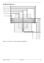
Страница 21: ...SB700U 11 SE3207 SMA America 3 5 Wall Mounting Bracket Figure 3 3 Dimensions of the wall mounting bracket...
Страница 24: ...3 8 SMA America SB700U 11 SE3207 11 Verify that the Sunny Boy 700U is firmly mounted in place...
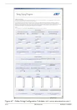
Страница 38: ...4 14 SMA America SB700U 11 SE3207 Figure 4 7 Online String Configuration Calculator at www sma america com...
Страница 46: ...4 22 SMA America SB700U 11 SE3207...
Страница 50: ...6 2 SMA America SB700U 11 SE3207 Figure 6 1 The Sunny Boy LED Status Indicator...
Страница 84: ...8 6 SMA America SB700U 11 SE3207...
Страница 85: ......

