4-18
SMA America
SB700U-11:SE3207
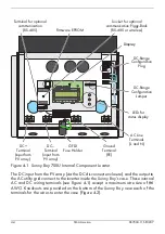
Connecting Communication Cables
Various data-communication options are available for the Sunny Boy 700U. These
options are provided in the form of Piggy-Back modules that can be installed and
connected either at the time the inverter is installed or at any time thereafter. Refer
to the instructions included with the communication module for installation
procedures.
The following subsection provides instructions for connecting communication cables
of RS-485 between a Sunny Boy with a communication module and a personal
computer (PC).
RS-485 Communication
RS-485 is a communication standard for bidirectional transmission of data between
one or more Sunny Boy inverters and a PC.
Note:
All Sunny Boy inverters are capable of RS-485 commu-
nication as long as the requirements below are met. You can
mix different Sunny Boy models on the RS-485 communica-
tion bus.
Requirements for RS-485 Communication:
• The Sunny Boy 700U must be equipped with an RS-485 Piggy-Back communication mod-
ule.
• A 3 conductor cable no longer than 4000 feet (1200 meters) with a common shield, and
a wire size no smaller than 24 AWG. The cable must consist of 2 twisted pairs with a
common shield surrounding all 4 wires.
Connecting an RS-485 Cable
Use the following procedure to install an RS-485 data-communication cable:
Note:
The following steps describe how to connect one Sun-
ny Boy inverter to an RS-485 bus. For information on connect-
ing more than one inverter to an RS-485 bus, please see
“Technical Note: RS-485 Communication” in the Tech Up-
dates section of our web site at www.sma-america.com
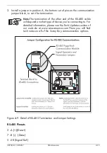
1. Connect the three insulated wires of the RS-485 cable to terminals 2, 5, and 7
of the communication terminal block. Record the wire color used for each of
the terminals.
2. Connect the shield of the cable to the Sunny Boy’s case.
Содержание Sunny Boy SB 700U
Страница 1: ...Sunny Boy SB 700U Installation Guide Version 1 1 SB700U 11 SE3207 TBE SB07U...
Страница 2: ...ii SMA America SB700U 11 SE3207...
Страница 14: ...1 6 SMA America SB700U 11 SE3207...
Страница 16: ...2 2 SMA AmericaSB700U 11 SE3207...
Страница 21: ...SB700U 11 SE3207 SMA America 3 5 Wall Mounting Bracket Figure 3 3 Dimensions of the wall mounting bracket...
Страница 24: ...3 8 SMA America SB700U 11 SE3207 11 Verify that the Sunny Boy 700U is firmly mounted in place...
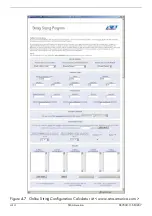
Страница 38: ...4 14 SMA America SB700U 11 SE3207 Figure 4 7 Online String Configuration Calculator at www sma america com...
Страница 46: ...4 22 SMA America SB700U 11 SE3207...
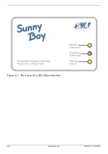
Страница 50: ...6 2 SMA America SB700U 11 SE3207 Figure 6 1 The Sunny Boy LED Status Indicator...
Страница 84: ...8 6 SMA America SB700U 11 SE3207...
Страница 85: ......

