13.3.2.5 Active Power Limitation via Standard Signal: WCnstNomAnIn Mode
The active power limitation is set via an analog signal at the input terminals for the setpoint. This is usually implemented
by a ripple control signal. The electrical current strength of the connected signal determines the nominal active power.
The analog measured values must be between 4 mA and 19 mA. If the analog signal is less than 2 mA, an error
message will be displayed in the instantaneous value
P-WModFailStt
.
Signal
Power limit
Description
< 2 mA
Last valid value or
Pmax
after restart
Signal is in the invalid range.
2 mA to 4 mA
0 kW
No power is fed into the grid.
4 mA to 19 mA 0 kW to
Pmax
The energy fed into the grid is determined by a character-
istic curve.
> 19 mA
Pmax
The energy fed into the grid equals
Pmax
.
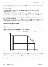
The analog value is converted to a setpoint for power limitation. Here, the parameter
Pmax
forms the end point of the
linear characteristic curve.
13.3.3 Reactive Power Control
13.3.3.1 No Reactive Power Control: Off Mode
The reactive power setpoint is limited to 0 kVAr. This setpoint cannot be controlled.
13.3.3.2 Reactive Power Control with Setpoint Command via Modbus Protocol:
VArCtlCom Mode
The reactive power setpoint is received by the communication unit and transmitted to the inverter. The setpoint is
transmitted as a percentage value and converted to kVAr in the device. If the inverter has not received any signal for
five minutes, the error message
Q-VArModFailStt
will be displayed.
13.3.3.3 Reactive Power Control with Setpoint Command via Modbus Protocol:
PFCtlCom Mode
The reactive power setpoint is received by the communication unit and transmitted to the inverter. The setpoint is
transmitted as a displacement power factor cos φ. If the inverter has not received any signal for the last five minutes, an
error message will be displayed in the instantaneous value
Q-VArModFailStt
.
13.3.3.4 Reactive Power Control with Absolute Value: VArCnst Mode
The reactive power setpoint is set via the parameter
Q-VAr
. The parameter
Q-VAr
is permitted to be within the range
from
‒Qmax
to
+Qmax
.
13.3.3.5 Reactive Power Control as a Percentage of the Nominal Power: VArCnstNom
Mode
The parameter
Q-VArNom
is used to set the reactive power setpoint in %. The parameter
Q-VArNom
refers to
Pmax
. If the calculated amount of reactive power exceeds the predefined value of
Qmax
, the power will be limited
to
Qmax
. If the calculated amount of reactive power falls below the predefined value of
‒Qmax
, the power will be
limited to
‒Qmax
.
13 Function Description
SMA Solar Technology AG
System Manual
MVPS22JP-SH-en-11
192
Содержание 1000-1SC
Страница 257: ......
Страница 258: ...SMA Solar Technology www SMA Solar com...


