


Appendix A
IN610 DIO Interface Module
80
IN
finity
610
User’s Guide
A.1.
Digital Inputs
The digital inputs (Terminal 1–Terminal 4) can be used as general purpose
inputs or to trigger the reader for tag reading. Unused or open digital inputs
are pulled high to +15 Vdc inside the reader. The DIO interface module has
an LED provided in series with each digital input line that lights when the
input is activated by an external source.
To activate the input, pull it low (0 Vdc) with an external device or
connection to ground that can sink 2.5 mA. No voltage higher than +15 Vdc
or lower than 0 Vdc should ever be connected to a digital input. Examples of
typical motion detectors installed as tag read trigger devices are shown in
diagrams later in this appendix.
Configuring the reader for digital input triggered reads is described in
Chapter 7 –
Configuring Digital Inputs and Outputs
.
A.2.
Digital Outputs
The digital outputs (Output 1 – Output 4) can be used as general purpose
outputs, to indicate tag reading activity, or to indicate the reader is
transmitting (RF On). Digital outputs are pulled high in the DIO interface
module to +12 Vdc through an LED and a series resistor. The LED is in
parallel with the output line and lights up when the output is activated by
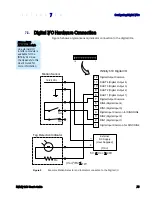
the reader. Refer to the following figure for a typical light stack installed as a
tag read indicator.
Caution:
No voltage higher than +15 Vdc or lower than 0 Vdc should ever be connected
to a digital output. The reader activates the output by pulling it low (0 Vdc) and
can sink up to 100 mA per line.
Configuring the reader for digital output activation on tag reads is described
later in this appendix.
A.3.
Input Power and Voltage Regulator
Input power is supplied by the +15 Vdc power supply and is passed through
the module to the reader (via terminal 18 and the o12 Vdc
regulator that su12 Vdc power to the board and to terminal 20).
The regulator has a tolerance of +/-5% and is capable of supplying 100 mA.
The total LED draw is 10 mA. Therefore, any total current draw for the board
should not exceed 75 mA.
Содержание INfinty 610
Страница 1: ......
Страница 8: ...Contents vi INfinity 610 User s Guide This page intentionally left blank ...
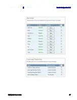
Страница 75: ...1 2 3 4 5 6 7 8 9 Reader Configuration Tool INfinity 610 User s Guide 67 ...
Страница 98: ...Appendix B IN610 DIO Interface Module 90 INfinity 610 User s Guide 8 Click the Change Settings button ...
Страница 106: ...Appendix C Disposal of the INfinity 610 Reader 98 INfinity 610 User s Guide This page intentionally left blank ...
Страница 107: ...INfinity 610 User s Guide This page intentionally left blank ...
Страница 108: ...INfinity 610 User s Guide ...


